
Page 218 - Industrial Power Engineering and Applications Handbook
P. 218
8/198 Industrial Power Engineering and Applications Handbook
during their run. (See Figure 6.38.) The couplings As the motor picks up speed, it builds up a centrifugal
can thus control the flow of air or fluid by force in the impeller, which causes the fluid to spill out
automatically regulating the speed of the drive and and fill the air gap between the two couplings. As the air
using only the amount of power that is needed by gap is filled only gradually, the runner engages with the
the load, which results in substantial energy saving. impeller gradually. The impeller converts the mechanical
See Section 6.15.2, which analyses the amount of power into hydraulic power and the runner converts this
energy saved. back to mechanical power. The transmission of power
from the runner to the load may be through flexible
Environment-friendly couplings couplings or belts. The torque transmitted during the
start is ro ortional to the square of the motor speed
?P
These couplings are totally enclosed and are suitable for (T N-). There may be small speed variations at
any environment prone to fire hazard, corrosion, dust or the secondary side, which will be due to slip between
any other pollutants. The controls can be provided the impeller and the runner (generally of the order of 2
remotely in a safer room and the pushbutton stations, - 5%). Thus the clutching at full speed is rigid. The
which can be easily made suitable for such environments, following illustrates the clutching sequence.
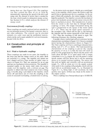
located with the drive. Consider a heavy inertia load such as a conveyor, having
characteristics according to Figure 2.13. Choose a standard
8.4 Construction and principle of motor having the characteristics shown in Figure 8.3.
The fluid coupling will have centrifugal characteristics
operation during start (T 0~ N2) as shown. The load-transmitting
characteristic of the coupling is pre-set (by varying
8.4.1 Fluid or hydraulic couplings the quantity of oil in it) so that the load will clutch at
point A in the graph figure by which time the motor will
These couplings are made in two parts, the impeller as reach about 80-90% of its rated speed with a torque
the inner part and the runner (rotor) as the outer. Both somewhere in its Tpo region. By now the motor's initial
are enclosed in a casing. The impeller and runner are inrush current will also droop and it will be operating
bowl shaped and have large number of radial vanes as almost at its normal running condition. The motor will
shown in Figure 8.4. They are separated by an air gap thus pick up lightly and smoothly with an accelerating
and have no mechanical interconnection. The impeller is torque, Tal, with no strain on it or the supply system.
mounted rigidly on the motor shaft while the runner After point A the coupling will gradually clutch with the
rotates over the impeller, with a uniform air gap. The load with an accelerating torque, T,?, as illustrated in
impeller is filled with fluid (mineral oil) from a filling Figure 8.3. Ta3 being high, it will accelerate the load
plug. A fusible plug is provided on the impeller, which quickly once again, without any strain on the motor or
blows off and drains out oil from the coupling in the the supply system.
event of sustained overloading, a locked rotor or gtalling. These couplings have been produced up to 10 000 kW,
N,, = Coupling speed
(Indicates coupling slip)
T, = Load starting torque
The load 1;
' clutches ,
here I I
I1
II
II
I
I
0 80% of N, N'
1- Motor speed 1 Speed
(primary speed)
(se~~~adda~~~~ed)
Figure 8.3 Smoother and quicker acceleration of heavy-duty loads with the use of a delayed-action coupling