
Page 273 - Industrial Power Engineering and Applications Handbook
P. 273
11/252 Industrial Power Engineering and Applications Handbook
temperature measurement by thermometer when 11.3 Procedure for testing
the machine is hot.
3 Load test In the following we describe a brief procedure to conduct
4 Overspeed test various tests and measurements and computation of the
5 Speed-torque and speed-current curves test results according to IEC 60034-1. (For more details
6 Vibration measurements and noise level tests to of the testing procedure the reader should refer to the
determine the machine’s mechanical performance
7 Verification of dielectric properties standard.)
(i) On the completed machine with wound coils or
formed coils: power frequency voltage withstand 11.3.1 Resistance measurement
or HV test At the beginning of the test the motor must be at ambient
(ii) Process tests during the manufacture of formed temperature. In this condition the temperature and
coils resistance of the windings should be recorded accurately.
(a) Test for insulation resistance - discussed in These values will be used later, with other test results, to
Section 9.5.3 evaluate the temperature rise and efficiency.
(b) Test for dielectric loss factor or dissipation factor Many types of winding connections are used, depending
tan Gfor rated voltages 5 kV and above upon the type of machine and the application for which
(c) Test for impulse voltage withstand for rated it is designed. The basic star and delta connections are
voltages 2.4 kV and above. most common, but a combination of these two with parallel
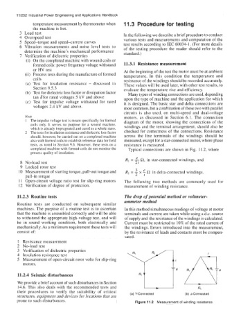
circuits is also used, on multi-speed and dual-voltage
Note motors, as discussed in Section 6.1. The connection
1 The impulse voltage test is meant specifically for formed diagram of the motor, showing the connections of the
coils only. It serves no purpose for a wound machine, windings and the terminal arrangement, should also be
which is already impregnated and cured as a whole mass.
2 The tests for insulation resistance and dielectric loss factor checked for correctness of the connections. Resistance
should, however, be carried out on a completed machine across the line terminals of the windings should be
also with formed coils to establish reference data for field measured, except for a star-connected motor, where phase
tests, as noted in Section 9.6. However, these tests on a resistance is measured.
completed machine with formed coils do not monitor the Typical connections are shown in Fig. 11.2, where
process quality of insulation.
R1 = e R, in star-connected windings, and
8 No-load test 2i
9 Locked rotor test
3
e
10 Measurement of starting torque, pull-out torque and R1 = - x - R in delta-connected windings.
pull-in torque 2 i
11 Open-circuit voltage ratio test for slip-ring motors The following two methods are commonly used for
12 Verification of degree of protection. measurement of winding resistance.
11.2.3 Routine tests The drop of potential method or voltmeter-
ammeter method
Routine tests are conducted on subsequent similar
machines. The purpose of a routine test is to ascertain In this method simultaneous readings of voltage at motor
that the machine is assembled correctly and will be able terminals and current are taken while using a d.c. source
to withstand the appropriate high-voltage test, and will of supply and the resistance of the windings is calculated.
be in sound working condition, both electrically and Current must be restricted to 10% of the rated current of
mechanically. As a minimum requirement these tests will the windings. Errors introduced into the measurement,
consist of by the resistance of leads and contacts must be compen-
sated.
1 Resistance measurement
2 No-load test
3 Verification of dielectric properties
4 Insulation resistance test i
5 Measurement of open-circuit rotor volts for slip-ring
motors.
11.2.4 Seismic disturbances
We provide a brief account of such disturbances in Section
14.6. This also deals with the recommended tests and Rl
their procedures to verify the suitability of critical (a) Y-Connected (b) A-Connected
structures, equipment and devices for locations that are
prone to such disturbances. Figure 11.2 Measurement of winding resistance