
Page 275 - Industrial Power Engineering and Applications Handbook
P. 275
11/254 Industrial Power Engineering and Applications Handbook
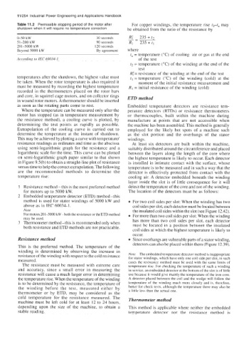
Table 11.2 Permissible stopping period of the motor after For copper windings, the temperature rise t2-t, may
shutdown when it will require no temperature correction be obtained from the ratio of the resistance by
0-50 kW 30 seconds
51-200 kW 90 seconds
201-S000kW 120 seconds
Beyond SO00 kW By agreement where
t, = temperature ["C) of cooling air or gas at the end
According to IEC 60034-1 of the test
t2 = temperature ("C) of the winding at the end of the
test
R;= resistance of the winding at the end of the test
temperatures after the shutdown, the highest value must tl = temperature ("C) of the winding (cold) at the
be taken. When the rotor temperature is also required it moment of the initial resistance measurement and
must be measured by recording the highest temperature R, = initial resistance of the winding (cold)
recorded in the thermometers placed on the rotor bars
and core, in squirrel cage motors, and on collector rings ETD method
in wound rotor motors. A thermometer should be inserted
as soon as the rotating parts come to rest. Embedded temperature detectors are resistance tem-
Where the temperature can be measured only after the perature detectors (RTDs) or resistance thermometers
motor has stopped (as in temperature measurement by or thermocouples, built within the machine during
the resistance method), a cooling curve is plotted, by manufacture at points that are not accessible when
determining the test points as rapidly as possible. the machine has been assembled. This method is generally
Extrapolation of the cooling curve is carried out to employed for the likely hot spots of a machine such
determine the temperature at the instant of shutdown. as the slot portion and the overhangs of the stator
This may be achieved by plotting a curve with temperature/ windings.
resistance readings as ordinates and time as the abscissa At least six detectors are built within the machine,
using semi-logarithmic graph for the resistance and a suitably distributed around the circumference and placed
logarithmic scale for the time. This curve can be plotted between the layers along the length of the core where
on semi-logarithmic graph paper similar to that shown the highest temperature is likely to occur. Each detector
in Figure 9.5(b) to obtain a straight-line plot of resistance is installed in intimate contact with the surface, whose
versus time to help the correct extrapolation. The following temperature is to be measured and in such a way that the
are the recommended methods to determine the detector is effectively protected from contact with the
temperature rise: cooling air. A detector embedded beneath the winding
layer inside the slot is of little consequence for it will
1 Resistance method - this is the most preferred method detect the temperature of the core and not of the winding.
for motors up to 5000 kW. The location of the detectors must be as follows:
2 Embedded temperature detector (ETD) method-this
method is used for stator windings of 5000 kW and For two coil sides per slot: When the winding has two
above as in IEC 60034-1. coil sides per slot, each detector must be located between
Note the insulated coil sides within the slot [see Figure 12.42).
For motors 201-SO00 kW-both the resistance or the ETD method For more than two coil sides per slot: When the winding
may be used.
3 Thermometer method-this is recommended only when has more than two coil sides per slot, each detector
must be located in a position between the insulated
both resistance and ETD methods are not practicable.
coil sides at which the highest temperature is likely to
occur.
Resistance method Since overhangs are vulnerable parts of a stator winding,
detectors can also be placed within them (Figure 12.39).
This is the preferred method. The temperature of the
winding is determined by observing the increase in
resistance of the winding with respect to the cold resistance Note The embedded temperature detector method is inappropriate
for stator windings, which have only one coil side per slot, in such
measured. cases the resistance method must be used with the same limits of
The resistance must be measured with extreme care temperature rise. For checking the temperature of such a winding
and accuracy, since a small error in measuring the in service, an embedded detector at the bottom of the slot is of little
resistance will cause a much larger error in determining use because it would give mainly the temperature of the iron core.
the temperature rise. When the temperature of the winding A detector placed between the coil and the wedge will follow the
is to be determined by the resistance, the temperature of temperature of the winding much more closely and is, therefore,
the winding before the test, measured either by better for check tests, although the temperature there may also be
thermometer or by ETD, may be considered as the a little less than the actual one.
cold temperature for the resistance measured. The Thermometer method
machine must be left cold for at least 12 to 24 hours,
depending upon the size of the machine, to obtain a This method is applicable where neither the embedded
stable reading. temperature detector nor the resistance method is