
Page 279 - Industrial Power Engineering and Applications Handbook
P. 279
11/258 Industrial Power Engineering and Applications Handbook
X (minus)+
0 -0.1 -0.2 -0.3 -0.4 -0.5 -0.6 -0.7 -0.8 -0.9 -1.0
0.6 1.1
0.5 1 .o
0.9
t 0.4 W2
=
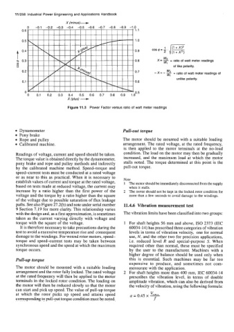
a 0.3 0.8 x= - ratio of watt meter readings
ul WI
8 of like polarity.
0.2 0.7 -x=-!% w, = ratio of watt meter readings of
unlike polarity.
0.1 0.6
x (plus) -
0 0.5
0 0.1 0.2 0.3 0.4 0.5 0.6 0.7 0.8 0.9 1.0
Figure 11.3 Power Factor versus ratio of watt meter readings
Dynamometer Pull-out torque
Pony brake
Rope and pulley The motor should be mounted with a suitable loading
Calibrated machine. arrangement. The rated voltage, at the rated frequency,
is then applied to the motor terminals at the no-load
Readings of voltage, current and speed should be taken. condition. The load on the motor may then be gradually
The torque value is obtained directly by the dynamometer, increased, and the maximum load at which the motor
pony brake and rope and pulley methods and indirectly stalls noted. The torque determined at this point is the
by the calibrated machine method. Speed-torque and pull-out torque.
speed-current tests must be conducted at a rated voltage
or as near to this as practical. When it is necessary to
establish values of current and torque at the rated voltage, Note
1 The motor should be immediately disconnected from the supply
based on tests made at reduced voltage, the current may when it stalls.
increase by a ratio higher than the first power of the 2 The motor should not be kept in the locked rotor condition for
voltage and the torque by a ratio higher than the square more than a few seconds to avoid damage to the windings.
of the voltage due to possible saturation of flux leakage
paths. See also Figure 27.2(b) and note under serial number 11.4.6 Vibration measurement test
9 Section 7.19 for more clarity. This relationship varies
with the design and, as a first approximation, is sometimes The vibration limits have been classified into two groups:
taken as the current varying directly with voltage and
torque with the square of the voltage. 1 For shaft heights 56 mm and above, IS0 2373 (IEC
It is therefore necessary to take precautions during the 60034- 14) has prescribed three categories of vibration
test to avoid a excessive temperature rise and consequent levels in terms of vibration velocity, one for normal
damage to the windings. For wound rotor motors, speed- use, N, and the other two for precision applications,
torque and speed-current tests may be taken between i.e. reduced level R and special-purpose S. When
synchronous speed and the speed at which the maximum required other than normal, these must be specified
torque occurs. by the user to the manufacturer. Machines with a
higher degree of balance should be used only when
Pull-up torque this is essential. Such machines may be far too
expensive to produce, and sometimes not com-
The motor should be mounted with a suitable loading mensurate with the application.
arrangement and the rotor fully locked. The rated voltage 2 For shaft heights more than 400 mm, IEC 60034-14
at the rated frequency will then be applied to the motor prescribes the vibration level, in terms of double
terminals in the locked rotor condition. The loading on amplitude vibration, which can also be derived from
the motor will then be reduced slowly so that the motor the velocity of vibration, using the following formula:
can start and pick up speed. The value of pull-up torque
at which the rotor picks up speed and attains speed a = 0.45 x %!!&
corresponding to pull-out torque condition must be noted. f