
Page 282 - Industrial Power Engineering and Applications Handbook
P. 282
Philosophy of quality systems and testing of electrical machines 11/261
100% of the rated voltage at intervals of 20%. The initial Until a few years ago, there was no widely accepted
value of tan &b.zVr and the increment Atan 6, i.e. standard for a voltage endurance test of the rotating
-
per
tan
3 [tan 60.6~~ 60~2~~1 measuring step should machines. Different agencies had adopted different
not exceed the values indicated in Table 11.5 for the practices on different assumptions, pending a final decision
rated voltages up to 11 kV. by the IEC working committee TC-2 of ZEC 60034-15.
It can be seen that up to 1.1 times the rated voltage The committee submitted its report in 1988 and the
(VJ, the tan 6 value remains almost constant, and at following test data, which are now universally adopted,
1.2Vr it increases slightly. At higher voltages it increases are based on this report.
sharply, and may become too high to cause a discharge The impulse test by means of a directly injected steep-
sufficient to char the insulation if this voltage is allowed fronted wave cannot be performed on a fully assembled
to exist for a longer period. machine as the bulk of the voltage, if the front of the
wave is less than Ips, will appear across the first few
11.4.9 Impulse! voltage withstand test of the turns only. Also, in the event of a failure, the whole
insulation system for rated voltages winding must be scrapped. The impulse test is therefore
performed on completed individual resin-rich formed coils
2.4 kV and above for machines only after insertion into the slots.
wound with formed coils The impulse test is basically an in-house coil insulation
As discussed in Section 17.5 a machine may be subjected withstand test for surge voltages and forms a part of the
to voltage surges due to external causes (lightning) or test requirement for HT machines with resin-rich formed
internal causes (switching). By the power frequency HV coils of 2.4 kV and above. Once the machine is assembled,
test or the dissipation factor, as in Section 11.4.8, or such a test is unnecessary, as it may not be able to reveal
insulation resistance tests as Section 9.5.3, the surge deficiencies, if any, in the insulation of the coils deep
withstand level of the insulating system cannot be inside the slots. Moreover, if a failure is noticed on the
determined. Hence, the need for an additional impulse assembled machine, there is no option but to scrap the
voltage withstand capability test of a coil for HV systems. whole winding.
The increasing application of vacuum- and gas-filled (SF6)
circuit breakers and contactors for switching of HT To assign the impulse level
machines, has led to the need for a surge voltage withstand
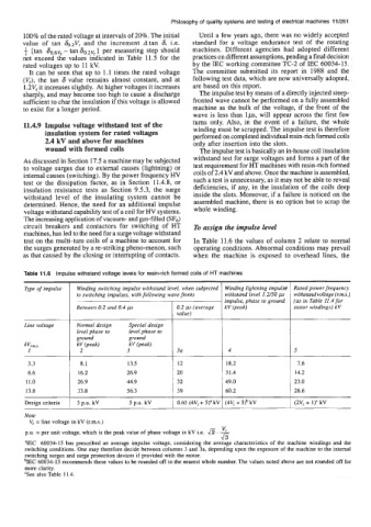
test on the multi-turn coils of a machine to account for In Table 11.6 the values of column 2 relate to normal
the surges generated by a re-striking pheno-menon, such operating conditions. Abnormal conditions may prevail
as that caused by the closing or interrupting of contacts. when the machine is exposed to overhead lines, the
Type of impulse Winding switching impulse withstand level, when subjected Winding lightning impulse Rated power frequency
withstand level 1.2/50 ps
to switching impulses, with following wave fronts kV (peak) withstand voltage (rm.s.)
'F 3 Special design value) 4 5
impulse, phase to ground
(as in Table 11.4 for
Between 0.2 and 0.4 p
0.2 p (average
stator windings) kV
Normal design
Line voltage
level phase to
level phase to
ground
ground
kV (peak)
kV (peak)
2
3a
7.6
18.2
12
11.0
8.1
13.5
16.2 26.9 20 31.4 14.2
26.9 44.9 32 49.0 23.0
13.8 33.8 56.3 39 60.2 28.6
Design criteria 1 3 p.u. kV 5 p.u. kV 1 0.65 (4Vr + 5)" kV I (4Vr + 5)b kV 1 (2V, + 1)'kV
Note
V, = line voltage in kV (r.m.s.)
vr -
p.u. = per unit voltage, which is the peak value of phase voltage in kV i.e.
43
WC 60034-15 has prescribed an average impulse voltage, considering the average characteristics of the machine windings and the
switching conditions. One may therefore decide between columns 3 and 3a, depending upon the exposure of the machine to the internal
switching surges and surge protection devices if provided with the motor.
bIEC 60034-15 recommends these values to be rounded off to the nearest whole number. The values noted above are not rounded off for
more clarity.
'See also Table 11.4.