
Page 281 - Industrial Power Engineering and Applications Handbook
P. 281
11/260 Industrial Power Engineering and Applications Handbook
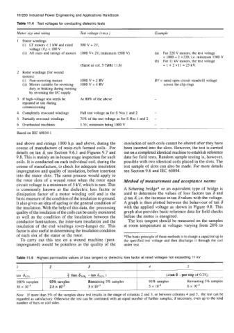
Table 11.4 Test voltages for conducting dielectric tests
Motor size and raring Test voltage (xm.s.) Examp le
Stator windings
(i) LT motors < 1 kW and rated 500 v + 2vr
voltage (V,) < 100 V
(ii) All sizes and ratings of motors 1000 V+ 2V,(minimum 1500 V) (a) For 220 V motors, the test voltage
= 1000 + 2 x220, Le. minimum 1500 V
(b) For 11 kV motors, the test voltage
(Same as col. 5 Table 11.6) = 1 + 2 x 11 = 23 kV.
Rotor windings (for wound
motors)
(i) Non-reversing motors IOOOV + 2 RV RV = rated open circuit standstill voltage
(ii) Motors suitable for reversing 1000 V + 4 RV across the slip-rings
duty or braking during running
by reversing the UC supply
If high-voltage test needs be At 80% of the above
repated at site during
commissioning
Completely rewound windings Full test voltage as for S Nos 1 and 2
Partially rewound windings 75% of the test voltage as for S Nos 1 and 2
Overhauled machines lSV, minimum being lo00 V
Based on IEC 60034-1
and above and ratings lo00 h.p. and above, during the insulation of such coils cannot be altered after they have
course of manufacture of resin-rich formed coils. For been inserted into the slots. However, the test is carried
details on tan 6, see Section 9.6.1 and Figures 9.1 and out on a completed identical machine to establish reference
9.8. This is mainly an in-house stage inspection for such data for field tests. Random sample testing is, however,
coils. It is conducted on each individual coil, during the possible with two identical coils placed in the slots. The
course of manufacture, to check for adequate insulation test sample of slots can also be made. For more details
impregnation and quality of insulation, before insertion see Section 9.6 and IEC 60894.
into the stator slots. The same process would apply to
the rotor slots of a wound rotor when the rotor open Method of measurement and acceptance norms
circuit voltage is a minimum of 5 kV, which is rare. This
is commonly known as the dielectric loss factor or A Schering bridge* or an equivalent type of bridge is
dissipation factor of a motor winding coil and is the used to determine the values of loss factors tan 6 and
basic measure of the condition of the insulation to ground. A tan 6, i.e. the increase in tan 6values with the voltage.
It also gives an idea of ageing or the general condition of A graph is then plotted between the behaviour of tan 6
the insulation. With the help of this data, the processing with the applied voltage as shown in Figure 9.8. This
quality of the insulation of the coils can be easily monitored graph also provides basic reference data for field checks
as well as the condition of the insulation between the before the motor is energized.
conductor laminations, the inter-turn insulation and the The loss tangent should be measured on the samples
insulation of the end windings (over-hangs) etc. This at room temperature at voltages varying from 20% to
factor is also useful in determining the insulation condition
of each slot of the stator or the rotor. *The basic principle of these methods is to charge a capacitor up to
To carry out this test on a wound machine (post- the specified test voltage and then discharge it through the coil
impregnated) would be pointless as the quality of the under test.
I 2 3 4 5
tan 60.2, + (tan 60.6, - tan 60.v,) (A tan 6 - per step of 0.2VJ
100% samples 95% samples Remaining 5% samples 95% samples Remaining 5% samples
30 x 2.5 x 1r3 3 x IO-’ 5 x 10⁻³ 6 x
Note If more than 5% of the samples show test results in the range of columns 2 and 3, or between columns 4 and 5, the test can be
regarded as satisfactory. Otherwise the test can be continued with an equal number of further samples, if necessary, even up to the total
number of bars or coil sides.