
Page 284 - Industrial Power Engineering and Applications Handbook
P. 284
Philosophy of quality systems and testing of electrical machines 11/263
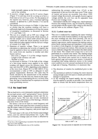
kinds normally appear on the first or the entrance subtracting the primary copper loss (ZitRl) at the
coil of the winding. temperature of the test from the input watts. If the values
2 In practice, voltage surges can be of various shapes of current and power are recorded, from about 130%
(Figure 17.2) and may even be so steep as to have a normal voltage downwards, and a graph of power against
front time as low as 0.2 ps or less. For the purpose of voltage plotted, the core loss can be separated, from
the impulse test, however, only a standard lightning friction and windage losses.
impulse, as defined by 1.2/50 (Section 17.6) can be Interception with the zero voltage axis, which represents
considered. friction and windage losses, may be found by plotting a
3 The impulse level in column 4 of Table 11.6 has been second graph with the square of the voltage as the abscissa
so chosen that the machine winding will have a and the watts as the ordinate (Figure 11.6),
sufficiently high level of insulation to fit into the system
of insulation coordination, as discussed in Section 11.5.1 Locked rotor test
17.11 and Table 11.6.
4 The test on a sample coil at 50% test voltage will This test is conducted by supplying the stator windings
indirectly represent the test on the whole machine, in with the rotor in the locked condition. In slip-ring motors,
that the sample coil is tested under almost the same the rotor windings are also short-circuited. The test is
conditions to which the whole machine would have carried out to determine the soundness of the rotor in
been subjected when applied with the full test voltage squirrel cage motors, and to measure the starting current,
of column 4 of Table 11.6. power factor, starting torque and impedance. It also enables
5 Quantum of impulse voltage. There is no agreed us to draw a circle diagram, for single squirrel cage rotor
calculation to determine the severity of impulse that motors and wound rotor motors. This test may be carried
must be applied to these two sample entrance coils as out at a reduced voltage that will produce the rated current
this varies from one machine to another and other of the motor. The locked rotor torque test is not to be
factors such as: performed on a wound rotor motor. The starting torque
- Rise time tl (Figure 17.3) of the voltage impulse in a wound motor has no relevance, as it can be varied as
- Length of the entrance coil, and desired. The locked rotor current test is carried out on
- Number of turns. both squirrel cage and wound rotor motors. It should be
As discussed in Section 17.8 the bulk of the voltage recognized that testing induction motors in the locked
of a fast-rising impulse wave applied to the whole rotor condition involves unusual mechanical stresses and
winding will appear across the entrance turns. This a high rate of heating. Therefore, it is necessary that:
may vary from 40% to 90%, depending on the steepness
of the wave front. Report TC-2 of IEC 60034-15 has The direction of rotation be established prior to this
recommended a value of 50% as adequate to meet test.
general requirements. However, this value may be The mechanical method of locking the rotors must be
finally decided by the manufacturer of the machine strong enough to prevent injury to nearby personnel or
in consultation with the end user, based on the surge- damage to equipment.
generating source (interrupting device), its likely front As the windings are heated rapidly, the test voltage
time, the type of machine and its exposure to external must be applied as quickly as possible. Care should be
surge-generating sources. taken to ensure that the motor temperature does not
11.5 No load test
The no-load test is a very informative method to determine
the no-load current, core* and pulsationt losses, friction
and windage losses, magnetizing current and the no-
load power factor. The test also reveals mechanical
imbalance, if any, performance of the bearings, vibration
and noise level of the motor.
The motor is run on no load at a rated frequency and
voltage, until the watts input becomes constant (to ensure
that the correct value of friction loss is obtained). Readings
of line voltage, current, frequency and power input are
taken.
The watts input is the sum of the friction and windage
losses, core loss and no-load primary loss (I:,&). The
sum of friction, windage and core losses is obtained by windage losses 4
Friction and
*Core loss is the magnetizing or hysteresis loss and represents the
iron loss of the machine.
'Pulsation loss is the harmonic loss of the machine. Figure 11.6 No-load curves to separate out no-load losses