
Page 283 - Industrial Power Engineering and Applications Handbook
P. 283
11/262 Industrial Power Engineering and Applications Handbook
interrupting device has multiple re-strikes during a 15
switching operation, or at locations expected to have
surges higher than normal due to transferences, such as
at a power generating station. For all these conditions, t lo
higher values of impulse levels, as in column 3 of Table 2 5
11.6, may be chosen or surge suppressors installed. Ql
so
0,
P
Test recommendations D
2 -5
1 The test coils should be finally processed and then 8
embedded into the slots. T -1 0
2 The number of sample coils must be two unless
changed deliberately. -1 5
3 All coils that are subjected to this test must fulfil the 0 0.1 0.2 0.3 0.4 0.5 0.6 0.7 0.8
test requirements. In the case of a failure, investigations Time (milliseconds) +
must be carried out to establish the cause and the
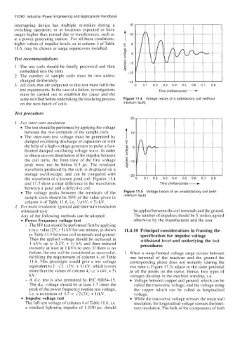
same rectified before undertaking the insulating process Figure 11.4 Voltage traces of a satisfactory coil (without
on the next batch of coils. interturn fault)
Test procedure
20
1 For inter-turn insulation
The test should be performed by applying the voltage
between the two terminals of the sample coils.
The inter-turn test voltage must be generated by T lo
damped oscillating discharge of capacitors or with 5
the help of a high-voltage generator to pulse a fast- go
fronted damped oscillating voltage wave. In order B ....
P
to obtain an even distribution of the impulse between D
the coil turns, the front time of the first voltage 2 -10
2
peak must not be below 0.5 ,us. The resultant T
waveform produced by the coil, is displayed on a
storage oscilloscope, and can be compared with -20
the waveform of a known good coil. Figures 11.4 0 0.1 0.2 0.3 0.4 0.5 0.6 0.7 0.8
and 11.5 show a clear difference in the waveforms Time (milliseconds)-
between a good and a defective coil.
The voltage peaks between the terminals of the Figure 11.5 Voltage traces of an unsatisfactory coil (with
sample coils should be 50% of the value given in interturn fault)
column 4 of Table 11.6, i.e. '/2(4Vr + 5) kV.
2 For main insulation (ground and inter-turn insulation
withstand test) be applied between the coil terminals and the ground.
Any of the following methods can be adopted: The number of impulses should be 5, unless agreed
Power frequency voltage test otherwise by the manufacturer and the user.
- The HV test should be performed first by applying
r.m.s. value (2Vr + 1) kV for one minute, as shown 11.4.10 Principal considerations in framing the
in Table 11.4 between coil terminals and ground. specification for impulse voltage
Then the applied voltage should be increased at withstand level and underlying the test
1 kV/s up to 2(2Vr + 1) kV, and then reduced
instantly at least at 1 kV/s to zero. If there is no procedures
failure, the test will be considered as successful, 1 When a steep-fronted voltage surge occurs between
fulfilling the requirement of column 4, of Table one terminal of the machine and the ground the
11.6. This procedure would give a test voltage corresponding phase does not instantly (during the
equivalent to 2 . 4 . (2 V, + 1) kV, which is even rise time t, Figure 17.3) adjust to the same potential
more than the values of column 4, i.e. > (4V, + 5) at all the points on the curve. Hence, two types of
kV. voltages develop in the machine winding, i.e.
- A d.c. test is also permitted by IEC 60034-15. Voltage between copper and ground, which can be
The d.c. voltage should be at least 1.7 times the called the transverse voltage, and the voltage along
peak of the power frequenc routine test voltage, the copper which can be called as longitudinal
i.e. a minimum of 1.7 x % 7 2(2Vr + 1)kV. voltage.
Impulse voltage test While the transverse voltage stresses the main wall
The full test voltage of column 4 of Table 11.6, Le. insulation, the longitudinal voltage stresses the inter-
a standard lightning impulse of 1.2/50 ps, should turn insulation. The bulk of the components of both