
Page 298 - Industrial Power Engineering and Applications Handbook
P. 298
Protection of electric motors 12/277
300
275
1 250
-
8 225
&
8 ,$go, Data at slip S
- Figure 12.4(a) Equivalent circuit diagram with a balanced
U
8 175 supply voltage (at slip S)
’
1561.
148 5:.
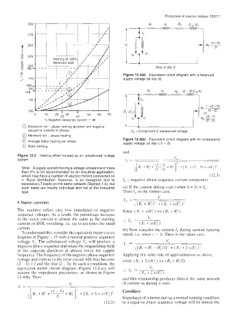
125
% Negafwe sequence current -
100
4o ’
0 10 20 i530 50 60 70 /,
@ Maximum hot - phase heating (positive and negative
sequence currents in phase) V, = Component of unbalanced voltage
@ Minimum hot - phase heating
Figure 12.4(b) Equivalent circuit diagram with an unbalanced
@ Average stator heating per phase supply voltage (at slip = 2 - S)
@ Rotor heating
and
Figure 12.3 Heating effect caused by an unbalanced voltage
c:
system I,, = .
~~~~
Note A supply system having a voltage unbalance of more
than 5% is not recommended for an industrial application,
which may have a number of electric motors connected on (12.3)
it. Rural distribution, however, is an exception due to I, = negative phase sequence current component
excessive LT loads on the same network (Section 7.6), but
such loads are mostly individual and not of the industrial (a) If the current during start (when S = 1) = I,,
type. Then I,, in the former case,
vr
I,, = ___
Stator currents \(R, +RI)’ +(XI +SAX;)’
~~~~
The machine offers very low impedance to negative Since (Xi + FFX; ) >> (R, + Ri )
sequence voltages. As a result, the percentage increase
in the stator current is almost the same as the starting ... v,
current on DOL switching. i.e. six to ten times the rated = (Xi + ssx; )
current. (b) Now consider the current I, during normal running
To understand this, consider the equivalent motor circuit speed, Le. when s = 0. Then in the latter case,
diagram of Figure 1.15 with a normal positive sequence
voltage Vr. The unbalanced voltage V, will produce a VU
negative phase sequence and rotate the magnetizing field I,, -- __- ~~
,/[R, +Ri -Ri/2]’ +(Xi +2ssXi)?
in the opposite direction at almost twice the supply
frequency. The frequency of the negative phase sequence Applying the same rule of approximation as above,
voltage and current in the rotor circuit will thus become since (X, + 2ssX? ) >> (R, + R;/2)
(2 - S) xfand the slip (2 - S). In such a condition, the
equivalent motor circuit diagram (Figure 12.4(a)) will :. I, = V”
assume the impedance parameters. as shown in Figure (Xi + 2 ssx; )
12.4(b). Thus and this relationship produces almost the same amount
of current as during a start.
vr
1. = ~~-___~~~
~
Corollary
Impedance of a motor during a normal running condition
(1 2.2) to a negative phase sequence voltage will be almost the