
Page 301 - Industrial Power Engineering and Applications Handbook
P. 301
12/280 industrial Power Engineering and Applications Handbook
1 A fault condition, such as a short-circuit between phases.
2 A ground fault condition.
3 A prolonged starting time.
4 A stalling or locked rotor condition: An undervoltage,
an excessive load torque or a mechanical jamming of
the driven equipment may cause this. It may lock the
rotor during a start, due to an inadequate starting torque.
Such a situation is known as stalling and results in a
near-locked rotor condition (see Figure 12.6). At
reduced voltage start the motor will stall at speed N,
and will not pick up beyond this. If the motor was
already running and the motor torque takes the shape
of curve B due to a voltage fluctuation, the motor
may not stall but may operate at a higher slip S2.
Although, this is not a stalling condition it may cause Speed -
severe overloading. At high slips, the current I, traces Kl
back the starting current curve as on DOL as illustrated,
and may assume a very high value.
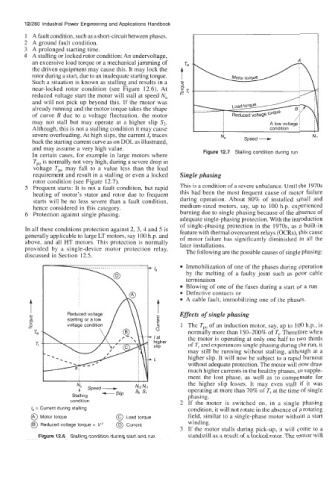
In certain cases, for example in large motors where Figure 12.7 Stalling condition during run
Tpo is normally not very high, during a severe drop in
voltage Tpo may fall to a value less than the load
requirement and result in a stalling or even a locked Single phasing
rotor condition (see Figure 12.7).
5 Frequent starts: It is not a fault condition, but rapid This is a condition of a severe unbalance. Until the 1970s
heating of motor's stator and rotor due to frequent this had been the most frequent cause of motor failure
starts will be no less severe than a fault condition, during operation. About 80% of installed small and
hence considered in this category. medium-sized motors, say, up to 100 h.p. experienced
6 Protection against single phasing. burning due to single phasing because of the absence of
adequate single-phasing protection. With the introduction
of single-phasing protection in the 1970s, as a built-in
In all these conditions protection against 2, 3, 4 and 5 is feature with thermal overcurrent relays (OCRs), this cause
generally applicable to large LT motors, say 100 h.p. and of motor failure has significantly diminished in all the
above, and all HT motors. This protection is normally later installations.
provided by a single-device motor protection relay, The following are the possible causes of single phasing:
discussed in Section 12.5.
Immobilization of one of the phases during operation
I, by the melting of a faulty joint such as poor cable
x Blowing of one of the fuses during a start or a run
termination
Defective contacts or
A cable fault, immobilizing one of the phases.
t
Reduced voltage / \\ * Effects of single phasing
starting or a low g
voltage condition 1 The Tpo of an induction motor, say, up to 100 h.p., is
0 normally more than 150-200% of T,. Therefore when
I at the motor is operating at only one half to two thirds
higher of T, and experiences single phasing during the run, it
slip
may still be running without stalling, although at a
higher slip. It will now be subject to a rapid burnout
1,
without adequate protection. The motor will now draw
much higher currents in the healthy phases, to supple-
ment the lost phase, as well as to compensate for
the higher slip losses. It may even stall if it was
Speed- Nrz N,l operating at more than 70% of T, at the time of single
Stalling -SI@ s, phasing.
condition 2 If the motor is switched on, in a single phasing
la = Current during stalling condition, it will not rotate in the absence of a rotating
@ Motor torque @ Load torque field, similar to a single-phase motor without a start
winding.
@ Reduced voltage torque = Vz @ Current
3 If the motor stalls during pick-up, it will come to a
Figure 12.6 Stalling condition during start and run standstill as a result of a locked rotor. The motor will