
Page 306 - Industrial Power Engineering and Applications Handbook
P. 306
Protection of electric motors 12/285
200 se
(a) Tripping under a healthy condition.
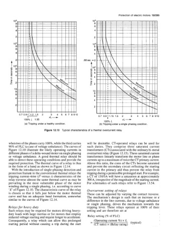
Figure 12.13 Typical characteristics of a thermal overcurrent relay
when two of the phases carry loo%, while the third carries will be desirable. CT-operated relays can be used for
90% of FLC (a case of voltage unbalance). The curves of such duties. They comprise three saturated current
Figure 12.10 illustrate the likely operating currents in transformers (CTs) associated with the ordinary bi-metal
different phases of a delta-wound motor on single phasing overcurrent relay (Figure 12.15). These saturated current
or voltage unbalance. A good thermal relay should be transformers linearly transform the motor line or phase
able to detect these operating conditions and provide the currents up to a maximum of twice the CT primary current.
required protection. The thermal curve of a relay is thus Above this ratio, the cores of the CTs become saturated
in the form of a band as shown in Figure 12.14. and prevent the secondary circuit reflecting the starting
With the introduction of single-phasing detection and current in the primary and thus prevent the relay from
protection feature in the conventional thermal relays the tripping during a permissible prolonged start. For example,
tripping current-time (Z2 versus t) characteristics of the a CT of 150/5A will have a saturation at approximately
relay traverse almost the same thermal curve as may be 300A, irrespective of the magnitude of the starting current.
prevailing in the most vulnerable phase of the motor For schematics of such relays refer to Figure 13.54.
winding during a single phasing, i.e. according to curve
‘X’ of Figure 12.10. The characteristic curve of the relay Overcurrent setting of relays
is chosen so that it falls just below the motor thermal These can be adjusted by varying the contact traverse.
curve and has an adequate band formation, somewhat The mechanism’s design is such that an increase or a
similar to the curves of Figure 12.14. difference in the line currents, due to voltage unbalance
or single phasing, drives the mechanism towards the
Relays for heavy duty tripping lever. These relays operate at 100% of their
Such relays may be required for motors driving heavy- setting and are therefore set at
duty loads with large inertias or for motors that employ
reduced voltage starting and require longer to accelerate. Relay setting (% of FLC)
Consequently, a relay which can allow this prolonged (Operating current %) x I,
starting period without causing a trip during the start - - (CT ratio) x (Relay rating) (typical)