
Page 311 - Industrial Power Engineering and Applications Handbook
P. 311
12/290 Industrial Power Engineering and Applications Handbook
In other words, the current-time (1’ - t) characteristics (b) Short-circuit currents up to the breaking capacity of
of fuses at C should lie below that of fuses at B, and the breaker should also be cleared by tripping the
that of fuses at B, should lie below the fuses at A. breaker through the in-built releases and not through
etc., throughout their operating range. the fuses.
(c) Short-circuit currents in excess of the breaking
Coordination of fuses with an overcurrent relav or capacity of the breaker alone should be cleared by
any other overcurrent protective device the operation of the fuses.
The selection of the fuses should be such that:
To achieve the above the characteristic of the fuses
(a) They do not operate during a start. should lie well above the characteristic of the overcurrent
(b) They do not operate against overloads as these are and short-circuit releases of the breaker for the lower
taken care of by the overcurrent relay or any other
overcurrent protective device. region of currents, such that only the breaker operates.
(c) They should isolate the supply to the motor in the However, it should lie well below the characteristic of
event of a fault sufficiently quickly before the fault the breaker in the higher region of currents to ensure that
causes damage to the connected equipment by burning the fuses operate sufficiently quickly and long before
and welding of contacts of the contactor or by causing the in-built releases. The breaker is thus prevented from
permanent damage or deformation to the bi-metal operating at currents that are in excess of its breaking
elements of the OCR. This is possible by ensuring capacity. Figure 12.22 illustrates such a coordination,
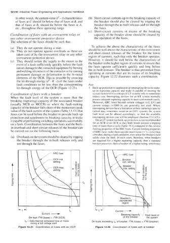
the let-through energy (1’ . R . t) of the fuses under
fault conditions to be less than the corresponding Note
let-through energy of the OCR (Figure 12.21). 1 Back-up protection to supplement an interrupting device to make-
up its rupturing capacity and make it capable of meeting the
Coordination of fuses with a breaker system fault level is a concept of LT systems only to sometimes
When the fault level of the system is more than the reduce cost. Interrupting devices for an HT system normally
breaking (rupturing) capacity of the associated breaker possess adequate rupturing capacity to meet system needs easily.
Moreover, HRC fuses beyond certain voltages (>I I kV) and
(usually MCB or MCCB) or when the fault-making current ratings (>IO00 A) are generally not used. Where
capacity of the breaker falls short of the momentary peak interrupting devices have a limitation in their rupturing capacity
value of the fault current of the system (Table 13.1 1) that (which may sometimes occur on an EHV system). the system
fuses can be used before the breaker to provide back-up fault level can be altered accordingly. so that the available
protection and supplement its breaking capacity, to make interrupting devices can still be employed (Section 13.4.1(5)).
it capable of performing switching operations successfully On an LT Fystem too bach-up protection ib nul recommended
on a fault. Coordination between the fuses and the built- for an ACB or an OCB as they both would possess a tripping
time of more than a cycle (Table 19.1 ) compared to the currem
in overload and short-circuit releases of the breaker can limiting properties of the HRC fuses. Current limiting properties
be carried out on the following basis: of HRC fuses make them operate much faster (< cycle) than
a breaker, during a fault condition. even when the breaker could
(a) Overloads on the system should be cleared by tripping safely clear the fault. In such cases, therefore, when breakers
the breaker through the in-built releases only and are required for a higher rupturing capacity than a standard
not through the fuses. breaker possesses, then a breaker of a higher rating. which may
ft
Current - Current --+ ! I
1st
Breaking capacity Fault level of
On fault 1’Rt (fuses) < I’Rt (OCR) of the breaker the system
fsl - Safe thermal withstand time of motor On faults exceeding /sc of breaker, /*Rt (fuses) c 1‘Rt (breaker)
during a full voltage start
Figure 12.21 Coordination of fuses with an OCR Figure 12.22 Coordination of fuses with a breaker