
Page 315 - Industrial Power Engineering and Applications Handbook
P. 315
Transformer p 7 It measures the values of VI, I, and temperature, 8
12/294 Industrial Power Engineering and Applications Handbook
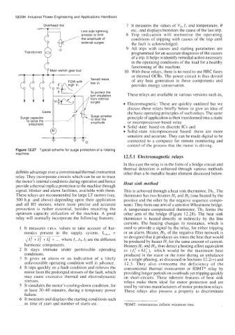
Overhead line
etc., and displays/monitors the cause of the last trip.
Line side lightning
8 Trip indication will memorize the operating
arrester to limit
-
the amplitude of
conditions of tripping with causes of the trip until
surges
external
the fault is acknowledged.
9 All trips with causes and starting parameters are
programmed for an accurate diagnosis of the causes
of a trip. It helps to identify remedial action necessary
in the operating conditions of the load for a healthy
( functioning of the machine.
Main switch gear bus IO With these relays, there is no need to use HRC fuses
d b or thermal OCRs. The power circuit is thus devoid
of any heat generation in these components and
provides energy conservation.
To protect the
,turn insulation These relays are available in various versions such as,
(1 -I \=
Electromagnetic: These are quickly outdated but we
discuss these relays briefly below to give an idea of
the basic operating principles of such relays. The same
u
u
Surge capacitor principle of application is then transformed into a static
to tame the amplitude or microprocessor-based relay
steepness
Solid state: based on discrete ICs and
Solid-state microprocessor based: these are more
sensitive and accurate. They can be made digital to be
'G
'G
-
-
connected to a computer for remote monitoring and
control of the process that the motor is driving.
Figure 12.27 Typical scheme for surge protection of a rotating
machine
12.5.1 Electromagnetic relays
In this case the relay is in the form of a bridge circuit and
thermal detection is achieved through various methods
definite advantage over a conventional thermal overcurrent other than a bi-metallic heater element discussed below.
relay. They incorporate circuits which can be set to trace
the motor's internal conditions during operation and hence Heat sink method
provide a thermal replica protection to the machine through
signal, blinker and alarm facilities, available with them. This is achieved through a heat sink thermistor, Th,. The
These relays are recommended for large LT motors (say, thermistor has two heaters HI and H2 (one heated by the
300 h.p. and above) depending upon their application positive and the other by the negative sequence compo-
and all HT motors, where more precise and accurate nent). They form one arm of a sensitive Wheatstone bridge.
protection is rather essential, besides requiring the A temperature-compensated thermistor, Th2 forms the
optimum capacity utilization of the machine. A good other arm of the bridge (Figure 12.28). The heat sink
relay will normally incorporate the following features: thermistor is heated directly or indirectly by the line
currents. The heating changes its resistance, which is
1 It measures r.m.s. values to take account of har- used to provide a signal by the relay, for either tripping
monics present in the supply system. Ir,,,s, = or an alarm. Heater, H2, of the negative filter network is
4 If + 1: + If + . . . where I,, I3,I, are the different so designed that it produces six times the heat that would
be produced by heater HI for the same amount of current.
harmonic components. Heaters HI and H2, thus detect a heating effect equivalent
2 It stays immune under permissible operating to (Z,? + 61: ), which would be the maximum heat
conditions. produced in the stator or the rotor during an unbalance
3 It gives an alarm or an indication of a likely or a single phasing, as discussed in Sections 12.2(v) and
unfavourable operating condition well in advance. 12.3. They also overcome the deficiency of the
4 It trips quickly on a fault condition and relieves the conventional thermal overcurrent or IDMT* relay by
motor from the prolonged stresses of the fault, which providing longer periods on overloads yet tripping quickly
may causc cxcessive thermal and electrodynamic on short-circuits. These inherent features of heat sink
stresses. relays make them ideal for motor protection and are
5 It simulates the motor's cooling-down condition, for used by various manufacturers of motor protection relays.
at least 30-60 minutes, during a temporary power These relays also possess a property to discriminate
failure.
6 It monitors and displays the starting conditions such
as time of start and number of starts etc. *IDMT: instantaneous definite minimum time