
Page 318 - Industrial Power Engineering and Applications Handbook
P. 318
Protection of electric motors 12/297
also memorize historical data and monitor a process more A typical relay is shown in Figure 12.29(b). These relays
closely. This relay can also be provided with a micro- can also be made digital to be connected to a central
processor. A microprocessor-based relay consists of PC control system for close monitoring and control of a
boards, a processor board and other electronic circuits. process. Now they can have much wider application,
such as better communication and information feedback
facilities, to optimize a process and maximize productivity.
R Y E For more details refer to Section 13.2.3 or contact the
manufacturers.
The following are the normal protections that may be
available in both-a solid-state or a microprocessor-based
relay, making them a single-device protection:
1 Prolonged starting protection. If the temperature rise
of the machine is more than 50% of the permitted rise
(0,) during the first start, the relay will lock out to
allow a pause and prevent a consecutive or a quick
restart until the machine cools sufficiently and the
total temperature rise 0, or f?,, does not exceed e,,
(equations (3.2) and (3.4)) during the next start. The
starting time is fed to the memory of the relay to
monitor the total starting time.
Likely settings - 8 versus tripping time, or time of
start versus tripping time-whichever occurs first.
Likely features - an advance alarm and an indication
before a trip.
2 Stalling or locked rotor protection. This is also detected
by the prolonged starting time as well as overheating
of the machine. It is possible that the machine was
already under operation and hot when it had stalled.
Under such a condition, the rotor operates at a high
frequency and is more vulnerable to damage. Since it
is not possible to create a replica of the rotor, separate
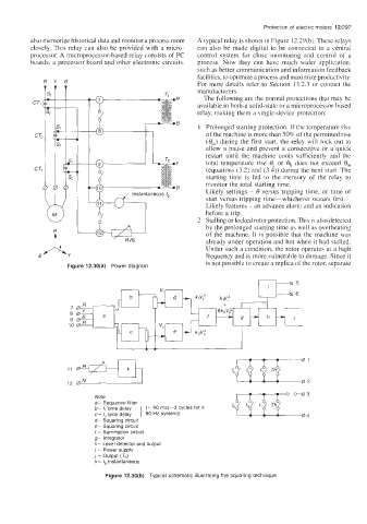
Figure 12.30(a) Power diagram
k
Note
a- Sequence filter
b- time delay (= 60 ms(-3 cycles for a
c- I, time delay ] 50 Hz system))
d- Squaring circuit
e- Squaring circuit
f - Summation circuit
g- integrator
h- Level detector and output
i - Power supply
1 - Output (Th)
k- Ig Instantaneous
Figure 12.30(b) Typical schematic illustrating the squaring technique