
Page 323 - Industrial Power Engineering and Applications Handbook
P. 323
12/302 Industrial Power Engineering and Applications Handbook
Motor starting current (A) -
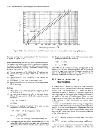
Figure 12.34 Fuse selection chart for 6.6 kV system for a motor with run-up time not exceeding 60 seconds
the motor starting curve and close below the thermal curve (v) Single-phasing setting. If set at loo%, can operate single-
as shown in Figure 12.33. phasing currents to the extent of
Static thermal relay (discrete ICs or microprocessor based) 110' = I,' +6/,'
For medium and large motors, 300 h.p. and above, this type or I, = 41.58%
of protective relay should be preferred to achieve optimum
utilization of the motor's capacity. Consider the available setting Note: The above exercise is merely an approach to the
ranges in the vicinity of selection of the most appropriate relay and its protective
settings for a particular machine. The exact selection of the
(a) Thermal overload unit: 70-130% of the CT rated current. relay and its setting will depend upon the type of relay, its
(b) Instantaneous (I,) unit: 600-1200% of the thermal unit sensitivity and protective features supplied.
setting.
(c) Instantaneous (1") unit: 200-600% of the thermal unit
setting. 12.7 Motor protection by
(d) Ground fault (I,) unit: 20% of the rated current
(e) Stalling protection unit: 150400% of the CT rated current, therm istors
2.5-25 seconds
A thermistor is a thermally sensitive, semiconductor
Settings solid-state device, which can only sense and not monitor
The overload unit setting: as worked out above, at 85A, (cannot read) the temperature of a sensitive part of
i.e. for 108.7% of I,. equipment where it is located. It can operate precisely
An instantaneous setting of 750% of the relay setting and consistently at the preset value. The response time is
should be appropriate, which can protect currents low and is of the order of 5-10 seconds. Since it is only
exceeding a temperature sensor, it does not indicate the temperature
7.5 x 1.087 x 123.2 A of the windings or where it is located but only its preset
condition.
or 1004 A This is a later introduction in the sensing of temperature
Unbalanced setting. If set at loo%, can operate compared to the more conventional types of temperature
unbalanced currents to the extent of devices available in an ernbcdded temperature detector
(ETD), such as a thermocouple or a resistance temperature
110' = 100' + 6 I,' (from equation (12.6)) detector (RTD) described below. Thermistors can be one
of the following types:
or I, = POZ 61°02
(i) NTC - having a negative temperature coefficient,
= 18.7%, i.e. a voltage unbalance of nearly 3% and
Stalling protection unit setting. The current unit is to be (ii) PTC - having a positive temperature coefficient.
set at 200-300%, and the time delay unit a little above
the starting time but less than the safe withstand stall The resistance-temperature characteristics of both these
time. types are shown in Figures 12.35 and 12.36. One can