
Page 325 - Industrial Power Engineering and Applications Handbook
P. 325
12/304 Industrial Power Engineering and Applications Handbook
Table 12.1 Curie points for a few PTC thermistors temperature up to 20O0C, such as required during impreg-
nation and curing of the stator windings. Depending upon
Winding temperature (“C) the reference temperature (Curie point), the thermistors
may be made of oxides of cobalt, manganese, nickel,
Insulation class E B F
barium and titanium. For motor protection, they are chosen
__f
according to the class of insulation used in the winding.
Temperature reference
For example, for a class E motor the switching point can
Steady overload condition 155 165 190 be chosen at 120°C and for class B at 130°C (refer to
Stalled condition 215 225 250 Table 9.1). These are tripping temperatures. For a pre-
warning by an alarm or annunciation they can be set at
Recommended reference temperature a slightly lower temperature so that an audible or visual
(Curie point) for thermistors (“C) indication is available before the motor trips to give an
Drop-off (tripping) Tp 130 140 160 opportunity to the operator to modify the operating
Warning Tp 110 120 140 conditions, if possible, to save an avoidable trip.
Since the thermistor circuit will trip the protective circuit
as soon as the thermistor current reduces drastically, it
provides an inherent feature to trip the protective circuit
even when the thermistor circuit becomes damaged or
open-circuited accidentally, extending a feature of ‘fail
to safety’.
A thermistor is very small and can be easily placed
inside the stator overhangs, bearings or similar locations,
wherever a control over the critical temperature is desired.
It is not provided in the rotor circuit (particularly squirrel
cage rotors), as noted earlier. This device is embedded in
the windings before impregnation, for obvious reasons.
For exact temperature monitoring, the thermistor is always
kept in contact with the winding wire. The number of
thermistors will depend upon the number of stator
windings and the specific requirement of warning or
tripping or both. Likely locations where a thermistor
can be placed in a motor are illustrated in Figure 12.39(a).
Such a device can actually predict the heating-up
conditions of a motor winding, at their most vulnerable
locations. It does not only provide total motor protection
Temperature (“C) - but also ensure its optimum capacity utilization. The
conventional methods of a motor’s protection through
an overload relay, a single-phasing preventor, a reverse
power relay or negative sequence voltage protection all
detect the likely heating-up conditions of the motor
windings under actual operating conditions, whereas a
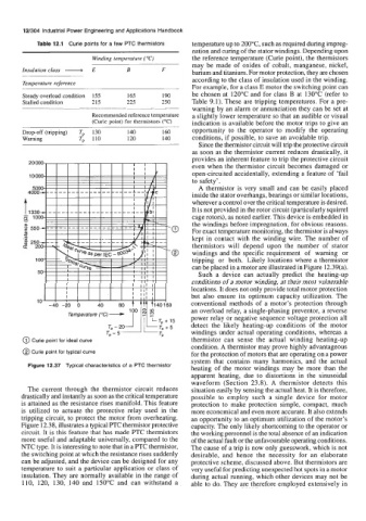
@ Curie point for ideal curve thermistor can sense the actual winding heating-up
condition. A thermistor may prove highly advantageous
@ Curie point for typical curve for the protection of motors that are operating on a power
system that contains many harmonics, and the actual
Figure 12.37 Typical characteristics of a PTC thermistor
heating of the motor windings may be more than the
apparent heating, due to distortions in the sinusoidal
waveform (Section 23.8). A thermistor detects this
The current through the thermistor circuit reduces situation easily by sensing the actual heat. It is therefore,
drastically and instantly as soon as the critical temperature possible to employ such a single device for motor
is attained as the resistance rises manifold. This feature protection to make protection simple, compact, much
is utilized to actuate the protective relay used in the more economical and even more accurate. It also extends
tripping circuit, to protect the motor from overheating. an opportunity to an optimum utilization of the motor’s
Figure 12.38, illustrates a typical PTC thermistor protective capacity. The only likely shortcoming to the operator or
circuit. It is this feature that has made PTC thermistors the working personnel is the total absence of an indication
more useful and adaptable universally, compared to the of the actual fault or the unfavourable operating conditions.
NTC type. It is interesting to note that in a PTC thermistor, The cause of a trip is now only guesswork, which is not
the switching point at which the resistance rises suddenly desirable, and hence the necessity for an elaborate
can be adjusted, and the device can be designed for any protective scheme, discussed above. But thermistors are
temperature to suit a particular application or class of very useful for predicting unexpected hot spots in a motor
insulation. They are normally available in the range of during actual running, which other devices may not be
110, 120, 130, 140 and 150°C and can withstand a able to do. They are therefore employed extensively in