
Page 330 - Industrial Power Engineering and Applications Handbook
P. 330
Protection of electric motors 12/309
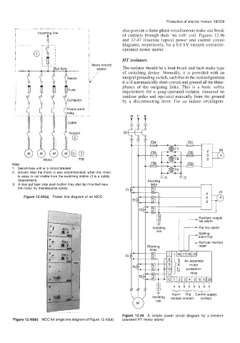
also provide a three-phase simultaneous make and break
I of contacts through their ‘no volt’ coil. Figures 12.46
I and 12.47 illustrate typical power and control circuit
I diagrams, respectively, for a 6.6 kV vacuum contactor-
I operated motor starter.
I HT isolators
- I Motor control The isolator should be a load-break and fault-make type
I
Bus bars
centre
/ of switching device. Normally, it is provided with an
I /’ integral grounding switch, such that in the isolated position
1’ it will automatically short-circuit and ground all the three-
phases of the outgoing links. This is a basic safety
requirement for a gang-operated isolator, mounted on
outdoor poles and operated manually from the ground
Contactor by a disconnecting lever. For an indoor switchgear,
Overcurrent
relay
Cable
Isolator
\
Motor P.B.
Note
1. Switch-fuse unit or a circuit breaker.
2. Isolator near the motor is also recommended, when the motor
is away or not visible from the switching station (it is a safety -G
requirement)
3. A stay put type stop push button may also be mounted near
the motor for maintenance safety
Figure 12.43(a) Power line diagram of an MCC
Isolating Pre trip alarm
link
Stalling
alarm/trip
Remote thermal
I links -
I Shortina
1 - 1 7 ) 16111181191
- Alarm Trip Control supply
isolating contact contact contact
link
Figure 12.44 A simple power circuit diagram for a breaker-
Figure 12.43(b) MCC for single line diagram of Figure 12.43(a) operated HT motor starter