
Page 331 - Industrial Power Engineering and Applications Handbook
P. 331
12/31 0 Industrial Power Engineering and Applications Handbook
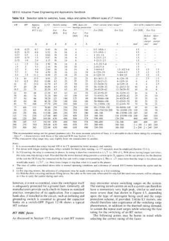
Table 12.4 Selection table for switches, fuses, relays and cables for different sizes of LT motors
kW HP Approx. IJd3 Switch rating HRC fuses for Over current relay range** Size ofA1 conductor cables
FLC at backup protection ~ ~~
415 V (I,) DOL LT ForDOL For Y/A F o T F F o r T
For Y/A
For
-
starter starter
A A A A A A
0.18 0.25 0.7 0.45 16 16 4 - 0.5-1/0.6-1 - 1.5 - -
0.25 0.33 0.9 0.52 16 16 4 - O.S-l/n.h-l - 1.5 - -
0.37 0.5 1.1 0.64 16 16 4 - 1-2/1-1.6 - 1.5 - -
0.55 0.75 1.5 0.87 16 16 6 - 1-2/1.5-2.5 - 1.5 - -
0.75 1.0 2.0 1.15 16 16 6 1-2/1.5-2.5 - 1.5 - -
~. -
1.1 1.5 2.6 1.50 16 16 6 - 1-5-Y2.54 - 1.5 - -
1.5 2 3.7 2.14 16 16 IO - 2-4/2.s4 - 1.5 - -
2.2 3 4.9 2.84 16 16 16 6 3-6/4-63 1.5-3/2.54 1.5 1.5 1.5
3.7 5 7.8 4.50 16 16 16 10 6-12/6-10 3-6/4-62 1.5 1.5 1.5
5.5 7.5 11.3 6.50 25 16 25 16 6-1219-14 4816-1 0 2.5 1.5 1.5
7.5 IO 15.5 8.95 25 25 25 25 10-16/13-21 6-1 2/6-10 4 2.5 1.5
9.3 12.5 19.0 11.00 63 25 35 25 12-24113-21 6-1 2/9-14 6 4 2.5
II 15 22.0 12.70 63 25 50 25 12-24/20-32 6-1 219- I4 6 4 2.5
15 20 29 16.80 63 63 63 35 16-32/20-32 12-24/13-2 I 10 6 4
18.5 25 35 20.20 63 63 63 50 244512842 12-24/20-32 I6 10 6
~ ~
22 30 40 23.20 63 63 63 50 24-45/3045 16-32/20-32 16 16 6
30 40 54 31.20 100 63 100 63 33-63145-70 24-45/2842 25 25 10
37 50 66 38.20 125 100 125 80 50-90160-100 2445/2842 3.5 25 16
45 60 80 46.20 250 100 160 100 50-90/60-100 32-63/45-70 50 35 25
55 75 100 57.70 250 250 200 125 70-110/90-150 32-63145-70 70 70 25
75 100 133 76.80 250 250 250 160 90-135/90-150 50-90/60-100 95 95 50
90 125 165 95.50 250 250 250 200 140-170/120-200 70-110/90-150 150 150 70
110 150 196 113.00 400 250 355 200 180-300 90-135/90-150 185 185 95
125 170 220 127.00 400 250 400 250 180-300 120-155/90-150 240 240 120
160 220 285 165.00 630 400 500 320 2nn-400 120-200 400 400 150
180 245 315 182.00 630 400 500 320 280400 120-200 400 400 185
200 270 350 205.00 630 400 630 355 280-400 180-300 2x 185 2x 185 240
220 300 385 222.00 630 400 630 400 350-500 180-300 2 x240 2 x 240 240
*The recommended ratings are for general guidance only. For more accurate selection of fuses, it is advisable to check these ratings by comparing
their I* - t characteristics with those of the selected OCR (see Section 12.4. I).
**The overcurrent relay range may vary slightly from one manufacturer to another.
Notes
1 It is recommended that relays beyond 100 A be CT operated for better accuracy and stability.
2 For drives with longer starting times, relays suitable for heavy-duty starting, i.e. CT operated, must be employed (Section 12.4.1).
3 In YlA starting, the relay is connected in phases. Its rating is therefore considered as I,/& i.e. 58% of I,. With drives having longer start times,
this relay may trip during a start. Provided that the motor thermal rating permits a current up to 21, (approx.) in the star position, for the duration
of the start the OCR may be connected on the line side with a range corresponding to 1, This is times more than the range in the phaaea and
would take nearly (&)’, Le. three times longer to trip than when it is used in the phases.
4 The sizes of cables considered above refer to normal operating conditions and a distance of around 10/15 metres between the starter and the
motor.
5 (i) For slip-ring motors, the selection of components may be made Corresponding to a Y/A switching.
(ii) With the short-circuiting and brush-lifting device, the cable on the rotor side, when rated for only half the rated rotor current, will be adequate,
as it has to carry the current during start only.
however, it is not so essential, since the switchgear itself may encounter severe switching surges on the system.
is adequately protected for a ground fault. Generally, all The starting inrush current on such a system can therefore
manufacturers provide such a built-in feature as standard have a momentary very high peak, similar to and even
practice, irrespective of its application. For a capacitor more severe than that shown in Figure 4.5, depending
bank also, if installed in the circuit, such an isolating and upon the type of interrupter being used and the surge
grounding switch is essential to ground the capacitor protection scheme, if provided. Unlike LT motors, one
banks on a switch-OFF. Figure 12.48 shows a typical should therefore take cognisance of the switching surge
HT isolator. phenomenon, in addition to the thermal rating demand,
to sustain the repeat start surges while selecting the fuse
HT HRC fuses rating rur the switching of an HT motor.
The following points may be borne in mind while
As discussed in Section 17.7, during a start HT motors selecting the correct rating of the fuses: