
Page 329 - Industrial Power Engineering and Applications Handbook
P. 329
12/308 Industrial Power Engineering and Applications Handbook
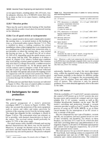
or two space heaters, totalling about 100-250 watts, may Table 12.3 Recommended sizes of cables for various sensing
be adequate, whereas, for a 10 000 kW motor there may and monitoring devices
be as many as four to six space heaters, totalling about
3500 watts. (A) LT motors Number of cables and sizes
(i) PTC, thermistors or embedded 12 x 2.5 mm2, 65011 100 V
12.8.5 Vibration probes resistance temperature detectors
(RTDs): for 6 sets of copper
These may be used to detect the hunting of the machine conductor cables
and to provide an audio-visual alarm for unusual running (2 cores for each set)
or for vibrations. (ii) PTC, thermistors or resistance 4 x 2.5 mm2, 650/1100 V
bearing temperature detectors
12.8.6 Use of speed switch or tachogenerator (RTDs): for 2 sets
(iii) Moisture detectors: 2 x 2.5 mm2, 650/1100 V
This is a speed-sensitive device and is employed to monitor For each detector
the starting time, t,, in normal motors or the heating-up (iv) Space heaters: 2 x 2.5 mm2, 650/1100 V
time, tE, in increased-safety motors (Section 7.13.2). This For each space heater
is installed to detect a stalling condition for critical
installations where a false tripping due to an overprotection (v) Speed switch: 2 x 2.5 mm2, 650/1100 V
For each switch
or a malfunction of the locked rotor protection relay is
not desirable, or where the starting time, t,, may exceed
the heating-up time, tE. The speed may be set at about (B) HT motors
Generally the same as for LT motors, except that the
10-30% of N,, depending upon the speed-torque curves recommended size of cables will be 6 mm2
of the motor and the load. The purpose is to detect a
speed, N, (Figure 12.6), where a locked rotor condition Note Wherever a cable lead connecting the above devices (such
may occur during a normal speed-up period. This situation as for RTDs) has to pass through a magnetic field, it may be screened
may arise due to a voltage fluctuation, a sudden excessive with tinned copper-braided wires to nullify the effect of stray fields.
torque or a load demand, etc. At the preset speed, the The field may distort the readings.
switch contacts open to energize a timer. If the motor is
not able to pick up within the motor thermal withstand
time, the timer will operate and actuate the tripping circuit universally, therefore, is to select the most appropriate
in conjunction with the locked rotor protection. When a relay, within the required range, from among the ranges
motor is statically controlled, this device is used for speed and brands available in the market for different ratings
correction through the feedback control system (Section of motors. Table 12.4 suggests the recommended relay
6.6). ranges, sizes of switches, fuses and cables for different
All these devices and their likely locations are indicated sizes of motors. This selection is only for general,
in Figure 12.39(a). The sizes of control cables to connect guidance. For a more detailed approach, refer to the notes
these devices are indicated in Table 12.3. to the table.
12.9.2 HT motors
12.9 Switchgears for motor
protection With the availability of 3.3 and 6.6 kV vacuum contactors
the control of HT motors up to 6.6 kV systems has now
become easier and economical, compact and even more
12.9.1 LT motors reliable. For 11 kV systems, vacuum as well as SF6
The general arrangement of a motor’s protection (Sulphur hbxafluoride) breakers can be used. The HT
switchgear (MCC*) is shown in Figure 12.43(b). This motor’s switching and protection through a vacuum
takes into account the protection of the main equipment contactor provides a replica of an LT system. The earlier
such as motors and cables and makes provision for practice of using an HT OCB, MOCB, or an air blast
isolation of the outgoing circuits from the incoming supply. circuit breaker for the interruption of an HT circuit is
The single line diagram for this switchgear is shown in now a concept of the past.
Figure 12.43(a). The overcurrent relays are selected, as The two comparatively new type of breakers, vacuum
far as possible, with thermal characteristics to those of and SF6 are exceptions and have gained favour in view
the motors. The overload setting should preferably be of their reliability and durability. For details on these
within 25-75% of the relay range. breakers, see Sections 19.5.5 and 19.5.6, which also deal
For small motors with a number of brands and varying with their switching behaviour and phenomenon of arc
thermal characteristics the above may not be practical. reignition. Figures 12.44 and 12.45 illustrate typical power
Moreover, to arrange the thermal curves for each relay and control circuit diagrams respectively, for a 6.6 kV
and motor and then match them individually for closer breaker-operated motor starter.
protection may also not be practical. The practice adopted The latest practice for up to 6.6 kV motors is to use an
HT load break, fault-making isolator in conjunction with
the appropriate type and size of HRC fuses, a vacuum
* MCC - motor control centre. For details refer to Chapter 13. contactor and a motor protection relay. The contactors