Page 324 - Industrial Power Engineering and Applications Handbook
P. 324

Protection of electric motors 12/303


                                        Response temp "C -                      3  160/0.36


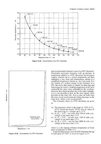
                                  Figure 12.35  Characteristic of  an NTC thermistor


                                                     note an exponential variation in case of an NTC thermistor.
                                                     Thermistor  resistance decreases  with  an  increase  in
                                                     temperature whereas in a PTC thermistor the resistance
                                                     remains constant up to a critical temperature and then
                                                     undergoes  a very  steep and instantaneous change  at a
                                                     predefined temperature, known as  the Curie point. It is
                                                     this  feature  of  a  sudden change  in the  resistance of  a
                                                     PTC thermistor that makes it suitable for detecting and
                                                     forecasting the motor's winding temperature at the most
                                                     vulnerable hot  spots when  embedded  in the  windings.
                                                     However, they can be installed only in the stator windings,
                                                     as it is not  possible to pick  up the rotor  signals when
                                                     provided  on the rotor side. Also to take out leads from
                                                     the rotor circuit would mean providing slip-rings on the
                                                     rotor shaft, which is not recommended.
                                                       The resistance values of  a PTC thermistor are given
                                                     as:

                                                     (a)  The resistance values in the range of -20°C  to (Tp-
                                                        20)"C should not exceed 250 0, with all values of
                                                        the measuring d.c. voltages up to 2.5 V.
                                                     (b)  At  (Tp - 5)"C  - not  more than  550 !2  with  a d.c.
                                                        voltage of not more than 2.5 V.
          ,a
                                Switching point
                                                     (c)  At  (T,, + 3°C - not  less than  1330 R with  a d.c.
                                 (Curie point) \
                                                        voltage of not more than 2.5 V.
                                                     (d)  At (Tp + 15)"C - not less than 4000 R with a d.c.
                                                        voltage of not more than 7.5 V.
                                                     where Tp. is the tripping reference temperature or Curie
                                                     point as indicated in Table 12.1.
                                                       A typical characteristic curve of a PTC thermistor having
           Figure 12.36  Characteristic of  a PTC thermistor   a Curie point of  120°C is shown in Figure  12.37.
   319   320   321   322   323   324   325   326   327   328   329