
Page 328 - Industrial Power Engineering and Applications Handbook
P. 328
Protection of electric motors la307
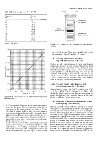
Table 12.2 Characteristics of a Pt - 100 RTD
Temperature Resistance
eoc a
0 100 Conductor of
50 119.40 top coil side
100 138.50
110 142.28
115 144.18
120 146.06 RTD or -,
125 147.94 thermo-couple
130 149.82 Conductor of
135 151.70 /-bottom coil side
140 153.57
145 155.45
150 157.32
Source IEC 60751
Figure 12.42 Location of a RTD or thermo-couple in a motor
winding
160
their simple wiring. They are generally preferred to
thermistors for large LT and all HT motors.
150
12.8.2 Bearing temperature detection
(by PTC thermistors or RTDs)
Motors are also recommended to have one bearing
- temperature detector in each bearing. This can be fitted
t 140
c:
within the threaded walls of the bearing that reach up to
130 the bottom of the bearing shell, i.e. close to where the
C heat is produced. Each detector may have two sets of
2 contacts, each having ‘2-NO’ contacts, rated for 5 A at
.Y
240 V a.c. and 0.5 A at 220 V d.c. One set can be set at
i? 120
a lower value to provide an audio-visual alarm and the
other at a higher value to trip the motor.
110 12.8.3 Coolant circuit water pressure and
temperature (moisture) detection
Water-cooled motors, type CACW (cooling type ICW
100
0 25 50 75 100 125 150 37 A 81 or ICW 37A 91) (Section 1.16, Table 1.12)
Temp (0)OC- should be fitted with moisture detectors to provide an
audio-visual alarm in the event of a leakage in the water
Figure 12.41 Characteristic of a Pt -100 resistance temperature circuit or a higher coolant temperature.
detector (RTD)
12.8.4 Detection of moisture condensation in the
windings (by space heaters)
PTC thermistors These are fragile and require usable
space in the slots. They are normally fitted in the Motors generally above 37.5 kW located in a humid
overhangs of the stator windings, as shown in Figure atmosphere or required to be stored idle for long periods
12.39(a). A sudden problem with the motor, causing may be provided with one or two and even more space
overheating, is instantly detected by an audio-visual heaters, depending upon the size of the motor, suitable
alarm or a trip. They are preferred for smaller motors. for 240 V, 1-$I a.c. supply, to maintain the motor’s internal
For larger motors, protection through monitoring is temperature slightly above the dew point to prevent
preferred to sensing only. Monitoring is possible through moisture condensation or deterioration of the insulation
RTDs or thermocouples. during a shutdown. The heaters are located inside the
RTDs or thermocouples These are normally embedded motor at the lower end of the stator so that they are
in the stator windings as illustrated in Figures 12.42 easily accessible and their removal and replacement
and 12.39(a). The winding temperature can now be presents no problem. The rating of total heating power
monitored continually and a temperature replica of may vary from about 100 watts to 3500 watts, depending
the machine obtained at any time. Figure 12.39(b) shows upon the size of the motor. For motors up to 400 kW, one