
Page 333 - Industrial Power Engineering and Applications Handbook
P. 333
12/31 2 industrial Power Engineering and Applications Handbook
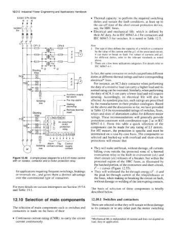
6.6 kV 3 Ph 50 Hz Thermal capacity: to perform the required switching
R Y B duties and sustain the fault conditions, at least up to
the cut-off time of the short-circuit protective device,
lsolato say, the HRC fuses.
sw Electrical and mechanical life: which is defined by
their AC duty. As in IEC 60947-4-1 for contactors and
IEC 60947-3 for switches. It is noted in Table 12.5.
c
Note
I The type of duty defines the capacity of a switch or a contactor
by the value of the current and the p.f. of the associated circuit,
it can make or break on fault. For values of currents and p.f.
for different duties, refer to the relevant standards as noted
above.
2 There are a few more utilization categories. For details refer to
IEC 60947-4- 1 .
In fact, the same contactor or switch can perform different
T4 duties at different thermal ratings and have corresponding
electrical* lives.
For instance, an AC3 duty contactor when performing
, the duty of a resistive load can carry a higher load and its
normal rating can be overrated. Similarly, when performing
the duty of AC4, it can carry a lower load and will require
- Auxiliary supply
fail alarm derating. Accordingly, its electrical life will also be
affected. As standard practice, such ratings are prescribed
link Stalling by the manufacturers in their product catalogues. Based
on the above and the discussions so far, we have provided
i components can be made for any rating of LT motors.
in Table 12.4 the recommended ratings of switches, fuses,
Remote thermal
ratings. These recommendations will generally provide
TI relays and sizes of aluminium cables for different motor
protection consistent with coordination type 2 as in IEC
60947-4-1. From this table a quick selection of the
For HT motors, the protection is specific and must be
determined on a case-by-case basis. The components so
selected and backed-up with overload and short-circuit
protections will ensure that
Trip
Alarm
Control
Isolating contact contact supply
They will make and break, without damage, all currents
contact
link
falling even outside the protected zone of a thermal
overcurrent relay or the built-in overcurrent (o/c) and
Figure 12.46 A simple power diagram for a 6.6 kV motor control short circuit (sk) releases of a breaker, but within the
with an isolator, contactor and a motor protection relay protected region of the HRC fuses, as illustrated by
the hatched portion, of the overcurrent and short-circuit,
I* - t curves (Figure 12.55).
for applications requiring frequent switchings, brakings They will withstand the let-through energy (Z2 . t) and
or reversals etc., and gives them a distinct advantage the pcak let-through current of the relays/releases or
over the conventional type of contactors. the fuses, when making or breaking the circuit on fault,
without damage or welding of the interrupting contacts.
For more details on vacuum interrupters see Section 19.5.6
and Table 19.1. The basis of selection of these components is briefly
described below.
12.1 0 Selection of main components 12.10.1 Switches and contactors
These are selected so that they will sustain without damage
The selection of main components such as switches and to its contacts or to any other part the motor switching
contactors is made on the basis of their
Continuous current rating (CMR): to carry the circuit *Mechanical life is independent of current and does not depend on
current continuously. load, duty or application.