
Page 334 - Industrial Power Engineering and Applications Handbook
P. 334
Protection of electric motors 12/31 3
240V AC
mtrol sup(:
-
sw \
CFI CF2 CFI CF;
LI
--
--_)
I
I
I
I
I - * To motor for
I winding and
Lock relay OUT I-' e 1 h4 perature etc.
- -
DC switching and ( I rol Thermistor Space
protection control . supply relay circuit heater
healthy
circuit circuit
AC control circuit for
auxiliaries
Figure 12.47 Typical schematic and control wiring diagram for power circuit of Figure 12.46
inrush current (ZSJ and possess a thermal capacity of
more than the fuse let-through energy (Figures 12.56
and 12.57).
12.10.2 Breakers (ACBs or MCCBs) (Figure 12.58)
While a fuse-free system is gradually gaining preference,
for all ratings, as discussed later, it is recommended that
a breaker (ACB or MCCB) be employed for large motors
of at least 300 h.p. and above to ensure better protection
for the motor.
12.10.3 Overcurrent relay (OCR)
It is necessary to coordinate the HRC fuses with the
overcurrent relay to ensure that during a fault the relay is
capable of withstanding the let-through energy of the
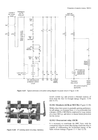
Figure 12.48 HT isolating switch (Courtesy: Siemens) fuses without damage (Figures 12.11 and 12.15).