
Page 337 - Industrial Power Engineering and Applications Handbook
P. 337
12/31 6 Industrial Power Engineering and Applications Handbook
250 I I I I I I 600
500
1 400
s
E
g
A 300
a,
L! 200
T
100
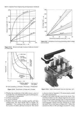
Symmetrical breaking current (kA) -
0
20
10
30
0
Contact gap (mm) - Figure 12.54 Comparison of arc energy produced by medium-voltage
0 5 10 15 20 circuit breakers
Figure 12.53 Dielectric strength of various media as a function
of contact gap
L, J t t
Current-
Breaking capacity i
Fault level of
of the breaker the system
On faults exceeding /sc of breaker, /*Rt (fuses) < /*Rt (breaker)
Figure 12.55 Coordination of fuses with a breaker Figure 12.56 Switch disconnector fuse unit (Courtesy: L&T)
Whether the installation of the cable is in air, a duct or is also provided in Appendix 1. For more details consult
in ground. This will determine the type of cable required, the cable manufacturer.
i.e. armoured or unarmoured. Length of the cable from the starter to the motor. This
Ambient temperature. will help to determine the voltage drop from the starter
Ist and its duration. to the motor terminals during a start. It must be limited
Number of power cables running together and their to only 2-3% of the rated voltage because the incoming
configuration. For more details refer to Chapter 16, receiving point voltage itself may already be less than
Appendix 1. The cooling of the cables is affected by the rated. This is illustrated in FigureA16.3. When the
the number of cables and their formation. This detail cumulative effect of all such drops exceeds 6%, it may