
Page 336 - Industrial Power Engineering and Applications Handbook
P. 336
Protection of electric motors 12/315
t
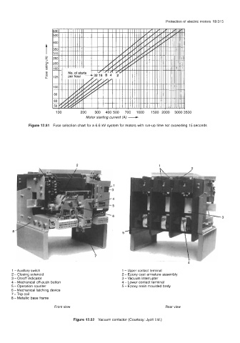
Figure 12.51 Fuse selection chart for a 6.6 kV system for motors with run-up time not exceeding 15 seconds
2 1
a 5
1 - Auxillary switch 1 - Upper contact terminal
2 -Closing solenoid 2 - Epoxy cast armature assembly
3 - On/off indicator 3 -Vacuum interrupter
4 - Mechanical off-push button 4 - Lower contact terminal
5 -Operation counter 5 - Epoxy resin moulded body
6 - Mechanical latching device
7 -Trip coil
8 - Metallic base frame
Front view Rear view
Figure 12.52 Vacuum contactor (Courtesy: Jyoti Ltd.)