
Page 317 - Industrial Power Engineering and Applications Handbook
P. 317
12/296 Industrial Power Engineering and Applications Handbook
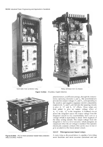
Solid state motor protection relay Relay withdrawn from its chassis
Figure 12.29(a) (Courtesy: English Electric)
potentiometers, at different settings, through the instanta-
neous operating elements /, and I,. The potentiometers
provide two output voltages V, and Vu, corresponding to
the positive and negative sequence current components
respectively. Ve and Vu are fed into the squaring circuits
to give kl . Vj and k, . V, effects. These values are
then added to give an output voltage effect of
kl . Vy' + 6k2 . V,' to the integrator. A feedback circuit
across the integrator causes the output voltage from the
integrator circuit to rise exponentially from zero to a
voltage which is equivalent to about 105% (typical) of
the relay setting current. The output voltage from the
integrator is fed to a level detector, which energizes an
output unit when the set voltage is reached. This operates
electrically separate contacts that can be used to trip or
give an alarm to the motor power circuit.
12.5.3 Microprocessor-based relays
Figure 12.29(b) PLC or micro-processor-based motor protection A static as discussed above is capab1e Of providing
relay (Courtesy: Alstom) more functions and more accurate operations and can