
Page 313 - Industrial Power Engineering and Applications Handbook
P. 313
la292 Industrial Power Engineering and Applications Handbook
R Y B
T T T
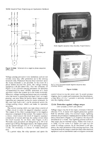
sequence voltage
---
Static negative sequence relay (Courtesy: English Electric)
I
N
Figure 12.23(a) Schematic for a negative phase sequence
(NPS) relay
Voltage-sensing preventors have limitations and are not
reliable since they offer protection up to the sensing
terminals only. Protection beyond these terminals up to
the motor terminals is not possible. In the event of a
phase failure beyond this point, the voltage-sensing PLC or micro-processor-based negative sequence relay
equipment will not detect this. (See the schematic of (Courtesy: Alstom)
Figure 12.24.) Current-sensing preventors are therefore
recommended for more reliable detection of a fault Figure 12.23(b)
anywhere within the system up to the motor terminals.
Moreover, voltage-sensing preventors may act erratically, control circuit to trip the starter unit. To avoid nuisance
when the motor is generating high back e.m.f. on single tripping, due to surges and momentary line disturbances,
phasing, and also when the power factor improvement a time delay of 4 to 7 seconds is normally introduced
capacitors are connected across the motor terminals. In into the tripping scheme.
this case high back e.m.f. can be produced across the
voltage-sensing relays, which can make its operation 12.4.6 Protection against voltage surges
uncertain. (for systems 2.4 kV and above)
The current-sensing solid-state type relays consist of
a filter circuit to sense the negative sequence current. Voltage surges may be of two types, external or internal
The output of this filter is proportional to the negative (Section 17.5). A motor will require protection against
sequence component of the current. The output is fed to both for absolute safety. For external surges, lightning
a sensor, which detects the level of negative sequence arresters are provided as standard practice at the receiving
component of current and trips the starter circuit when end as illustrated in Figure 12.27, to protect the electrical
this level exceeds the set limit. (See Figure 12.25.) installation as a whole. This lightning arrester will limit
Normally such preventors are designed up to 30 A for line surges due to external causes, within safe limits as
motors up to 20 h.p. For larger motors, the output current in Table 13.2 for series I or Tables 14.1 and 14.2 for
can be sensed through CTs of 5 A secondary (Figure series I1 voltage systems. In all likelihood it will also
12.26). 5A secondary is chosen to make detection protect the main insulation of the rotating machines. The
easy. insulation level of a motor is much less than other electrical
At a preset value, the relay operates and opens the equipment such as transformers and switchgears connected