
Page 310 - Industrial Power Engineering and Applications Handbook
P. 310
Protection of electric motors 12/289
Prospective current in amps (r.m.s) -
10 20 50 100 200 500 1000 2000 5000 10 000 20 000 50 000
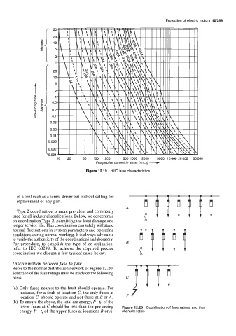
Figure 12.19 HRC fuse characteristics
of a tool such as a screw-driver but without calling for
replacement of any part.
Type 2 coordination is more prevalent and commonly
used for all industrial applications. Below, we concentrate
on coordination Type 2, permitting the least damage and
longer service life. This coordination can safely withstand
normal fluctuations in system parameters and operating
conditions during normal working. It is always advisable
to verify the authenticity of the coordination in a laboratory.
For procedure, to establish the type of co-ordination,
refer to IEC 60298. To achieve the required precise
coordination we discuss a few typical cases below.
Discrimination between fuse to fuse
Refer to the normal distribution network of Figure 12.20.
Selection of the fuse ratings must be made on the following
basis:
(a) Only fuses nearest to the fault should operate. For F, f
instance, for a fault at location C, the only fuses at
location C should operate and not those at B or A.
(b) To ensure the above, the total arc energy, Z2 . tt, of the
lower fuses at C should be less than the pre-arcing Figure 12.20 Coordination of fuse ratings and their
energy, I2 t, of the upper fuses at locations B or A. characteristics