
Page 305 - Industrial Power Engineering and Applications Handbook
P. 305
12/284 industrial Power Engineering and Applications Handbook
Bi-metallic" thermal relays (Figure 12.11) Micro
These have three heaters in series with the circuit. One switch
or more bi-metallic strips are mounted above these heaters,
which act as latches for the tripping mechanism or to
give an alarm signal if desired. The heaters may be heated
directly for small motors or through current transformers
(CTs) for medium-sized motors. Bending of the bimetallic
strips by heating, pushes a common trip bar in the direction
of tripping to actuate a micro-switch to trip the relay or
contactor. The rate of heating determines the rate of
movement and hence the tripping time, and provides an
inverse time characteristic. The power consumption of I
the bimetal heating strips varies from 2 to 2.5 watts/ @ During cold state
phase, i.e. a total of nearly 7.5 watts. I I
The latest practice of manufacturers is to introduce
a very sensitive differential system in the tripping
mechanism to achieve protection even against single-
phasing and severe voltage unbalances. In the relays with
single-phasing protection a double-slide mechanism is
provided. Under single phasing or a severe voltage
unbalance, the two slides of the relay undergo a differential
deflection. One slide senses the movement of the bi-
metal that has deflected to the maximum. while the other
senses the minimum. These slides are linked so that the
cumulative effect of their movement actuates a micro-
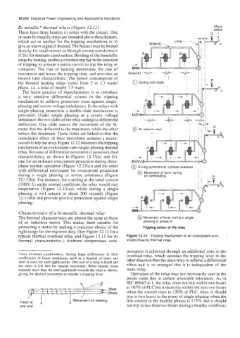
switch to trip the relay. Figure 12.12 illustrates the tripping
mechanism of an overcurrent-cum-single-phasing thermal
relay. Because of differential movement it possesses dual
characteristics, as shown in Figures 12.13(a) and (b),
one for an ordinary overcurrent protection during three-
phase normal operation (Figure 12.13(a)) and the other @ During symmetrical 3 phase overload
with differential movement for overcurrent protection
during a single phasing or severe unbalance (Figure a Movement of lever during I; -
an overloading
R
12.13(b)). For instance, for a setting at the rated current
(100% I,) under normal conditions the relay would stay
inoperative (Figure 12.13(a)), while during a single
phasing it will actuate in about 200 seconds (Figure
12.13(b)) and provide positive protection against single
phasing.
Characteristics of a bi-metallic thermal relay
The thermal characteristics are almost the same as those @ Movement of lever during a single
of an induction motor. This makes them suitablc for phasing in phase R
protecting a motor by making a judicious choice of the Tripping action of the relay
right range for the required duty. (See Figure 12.11 for a
typical thermal overload relay and Figure 12.13 for its Figure 12.12 Tripping mechanism of an overcurrent-cum-
thermal characteristics.) Ambient temperature com- single-phasing thermal relay
pensation is achieved through an additional strip in the
*Any bi-metal combination, having large differences in their overload relay, which operates the tripping lever in the
coefficients of linear expansion, such as a bimetal of brass and other direction than the main relay to achieve a differential
steel is used for such applications. One end of a strip is fixed and
the other is left free for natural movement. When heated, brass effect and is so arranged that it is independent of the
expands more than the steel and bends towards the steel as shown, main relay.
giving the desired movement to actuate a tripping lever. Operation of the relay may not necessarily start at the
preset value due to certain allowable tolerances. As in
IEC 60947-4-1, the relay must not trip within two hours
at 105% of FLC but it must trip within the next two hours
Steel when the current rises to 120% of FLC. Also, it should
Brass
Fixed/ at 1 1 Movement on heating trip in two hours in the event of single phasing when the
line current in the healthy phases is 115%, but it should
one end not trip in less than two hours during a healthy condition,