
Page 308 - Industrial Power Engineering and Applications Handbook
P. 308
Protection of electric motors 12/37
Note In view of the\e limitations, such relays did not find Nore It is also possible that in the operating region. beyond point
adequate acceptance under Indian conditions. As a result. their ‘A’. the curve of the thermal relay had fallen far below the motor
manufacture has been discontinued. thermal curve and had overprotected the motor. In other words. it
would have underutilized its capacity, in which caw, it will be
Large LT motors necessary to call for a reselection of the thermal relay that would
permit optimum utilization of the machine and. if necessary. giving
Large motors call for a more judicious selection of relays. it support through an IDMT relay to cover the underprotected region.
Unlike small motors, one cannot take for granted that Such a combination of an OCR and an IDMT relay is dsfactory
for detecting a system fault. overloading or a \tailing condition but
the thermal characteristics of the relay will be the same it cannot guarantee total protection. This combination does not
as that of the motor, and arbitrarily select any thermal trace a replica of the motor heating and cooling curve\. It can
relay. To make use of the optimum capacity of a motor simply detect the motor line currents and not the conditions that
and to yet protect it from all possible unfavourable may prevail within the windings, such as thwc as caused by an
operating conditions it is essential that the motor and the unbalance or a single phasing. Nor can they accurately assess the
relay’s thermal characteristics are matched closely. rotor’s heat caused by prolonged starting time or frequent starts.
Motors designed according to IEC 60034-1 are not The,e relays, at best, can be employed with instantaneous definite
meant for continuous overload running unless specifically minimum time to inverse and very inverse /‘-t characteristics to
match the machinc’s requirement as closely as po\sible. In view 01
designed for this. They should be closely protected with this. it will be worth while to have a single device protection against
the available devices. On the one hand, the protection overload and stalling which may occur due to undervoltage.
should be discriminating, to allow for starting current unbalance, single phasing or a ground fault. Such a protection is
surge and yet detect an overloading, unbalance, short- possible through a single device niotor protection relay. discussed
circuit or a ground fault before these cause damage to in Section 12.5.
the motor. On the other, it should ensure a full-load
operation of the motor. HT motors
A thermal relay cannot be set reliably to remain
inoperative at 100% of the full load current and then These call for a closer protection, which is possible through
operate instantly as soon as it exceeds this. A good thermal a single point motor protection relay (MPR). Since a
relay can be set to operate between 1 10% and 115% of single MPR provides protections against unfavourable
the /r, or even more if that is desirable, provided that the operating as well as fault conditions. we discuss this
thermal capacity of the motor can permit this. To ascertain relay separately in Section 12.5
this. availability of the motor thermal withstand curve is
essential. Accordingly, the relay can be set for the optimum
utilization of the motor by setting it for
Relay setting (% of FLC)
Motor maximum operating current (%)
- (typical)
-
1.1 or 1.15
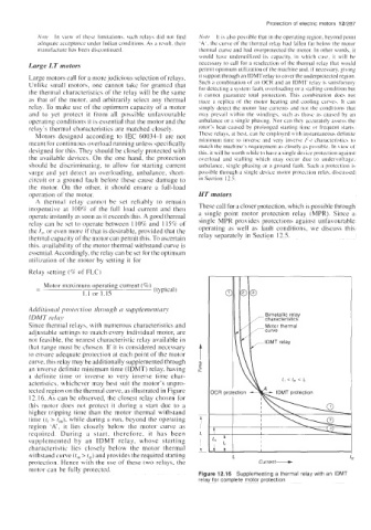
Additioriul protection through ci supplementun
IDMT re la^
Since thermal relays, with numerous characteristics and Motor thermal
ad,justable settings to match every individual motor, are
not feasible, the nearest characteristic relay available in
that range must be chosen. If it is considered necessary
to ensure adequate protection at each point of the motor
curve. this relay may be additionally supplemented through
an inverse definite minimum time (IDMT) relay, having
a definite time or inverse to very inverqe time char-
acteristics, whichever may best suit the motor’s unpro- f,, < fm < 1,
tected region on the thermal curve, as illustrated in Figure
12.16. As can be observed, the closest relay chosen for
this motor does not protect it during a start due to a
higher tripping time than the motor thermal withstand
time (tr > r,,,), while during a run, beyond the operating
region ‘A’, it lies closely below the motor curve as
required. During a start, therefore, it has been
supplemented by an IDMT relay, whose starting
characteristic lies closely below the motor thermal
withstand curve (rnl > t,r) and provides the required starting
protection. Hence with the use of these two relays, the
motor can be fully protected.
Figure 12.16 Supplementing a thermal relay with an IDMT
relay for complete motor protection