
Page 309 - Industrial Power Engineering and Applications Handbook
P. 309
12/288 Industrial Power Engineering and Applications Handbook
Commencement Current cut-off
of short-circuit r level
\\\ c 4 q
5
fs = Pre-arcing time
t, = Arcing time
tt = Total cut-off time Symmetrical
isc(peak) value of a fault current short-circuit
Peak
=
is, = Peak cut-off current by fuse current
Figure 12.17 Cut-off feature of an HRC fuse
12.4.2 Protection against fault conditions
Protection against short-circuits
(use of HRC fuses) 0.1 2
It is always desirable to protect a power circuit against o.2
short-circuits separately. HRC fuses are the immediate 1 2 4 6 8 10 20 io 40 6080
answer to such a requirement for small and medium- Symmetrical prospective --t
sized LT motors. They have a delayed action characteristic short-circuit current I,, (rms)(kA)
under an overload and are instantaneous against a short- Illustration:
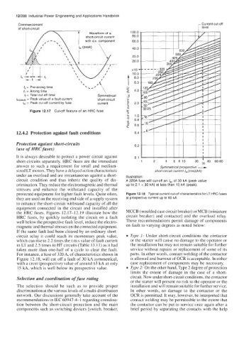
circuit condition and thus inherit the quality of dis- A 320A fuse will cut-off an lSc of 30 kA (peak value
crimination. They reduce the electromagnetic and thermal up to 2.1 x 30 kA) at less than 15 kA (peak).
stresses and enhance the withstand capacity of the
protected equipment for higher fault levels. Quite often, Figure 12.18 Typical current cut-off characteristics for LT HRC fuses
they are used on the receiving end side of a supply system at prospective current up to 80 kA
to enhance the short-circuit withstand capacity of all the
equipment connected in the circuit and installed after
the HRC fuses. Figures 12.17-12.19 illustrate how the MCCB (moulded case circuit breaker) or MCB (miniature
HRC fuses, by quickly isolating the circuit on a fault circuit breaker) and contactor] and the overload relay.
well below the prospective fault level, reduce the electro- These recommendations permit damage of components
magnetic and thermal stresses on the connected equipment. on fault to varying degrees as noted below:
If the same fault had been cleared by an ordinary short-
circuit relay it could reach its momentary peak value, Type 1: Under short-circuit conditions the contactor
which can rise to 2.2 times the r.m.s value of fault current or the starter will cause no damage to the operator or
in LT and 2.5 times in HT circuits (Table 13.1 1) as it had the installation but may not remain suitable for further
taken more than one-half of a cycle to clear the fault. service without repairs or replacement of some of its
For instance, a fuse of 320A, of characteristics shown in parts. In other words, contact welding of the contactor
Figure 12.18, will cut off a fault of 30 kA symmetrical, is allowed and burnout of OCR is acceptable. In either
with a crest (prospective) value of around 63 kA at only case replacement of components may be necessary.
15 kA, which is well below its prospective value. Type 2: On the other hand, Type 2 degree of protection
limits the extent of damage in the case of a short-
Selection and coordination of fuse rating circuit. Now under short-circuit conditions, the contactor
or the starter will present no risk to the operator or the
The selection should be such as to provide proper installation and will remain suitable for further service.
discrimination at the various levels of a multi-distribution In other words, no damage to the contactor or the
network. Our discussions generally take account of the OCR is permitted. It may, however, be interpreted that
recommendations in IEC 60947-4-1 regarding cooi-dina- contact welding may be permissible to the extent that
tion between the short-circuit protection and the main the contactor can be put to service once again after a
components such as switching devices [switch, breaker, brief period by separating the contacts with the help