
Page 314 - Industrial Power Engineering and Applications Handbook
P. 314
Protection of electric motors 12/293
R Y B N R Y B N
I1 E,
c -~
w i On Off
13
OIC &
L
On
Off
0
&
Single phasing SP trip Single phasing SP trip
-
-. ~--- . .
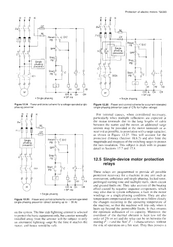
wgure 12.24 rower ana control scneme tor a voltage-operated single- Figure 12.26 Power and control scheme for a current-operated
F1-3 sN particularly when multiple reflections are expected at
phasing preventer single-phasing preventor (use of CTs for higher ratings)
For internal causes, when considered necessary,
the motor terminals due to the long lengths of cable
between the starter and the motor, an additional surge
arrester may be provided at the motor terminals or as
near to it as possible, in association with a surge capacitor,
as shown in Figure 12.27. This will account for the
protective distance (Section 18.6.2) and also limit the
Single magnitude and steepness of the switching surges to protect
phasing
preventor the turn insulation. This subject is dealt with in greater
detail in Sections 17.7 and 17.8.
12.5 Single-device motor protection
'1 6- These relays are programmed to provide all possible
relays
co --
protection necessary for a machine in one unit such as
overcurrent, unbalance and single phasing, locked rotor,
I 13
prolonged starting time and multiple starts, short-circuit
and ground faults etc. They take account of the heating
* SP trip effect caused by negative sequence components, which
may arise due to system unbalance, a fault in the motor
Single phasing
windings or a single-phasing condition. They are also
Figure 12.25 Power and control scheme for a current-operated temperature compensated and can be set to follow closely
single-phasing preventor (direct sensing up to = 30 A) the changes occurring in the operating temperature of
the machine, so that the machine will trip only when it
heats up beyond the permissible limits. It thus ensures
on the system. The line side lightning arrester is selected the optimum utilization of its capacity. Moreover, the
to protect the basic equipment only, but a motor normally overshoot of the thermal element is kept low (of the
installed away from the arrester will be subject to only order of 2% or so) and the relay can be set between the
an attenuated lightning surge by the time it reaches the starting I* - t and the 'hot' I* - t characteristics. without
motor, and hence would be safe. the risk of operation on a hot start. They thus possess a