
Page 316 - Industrial Power Engineering and Applications Handbook
P. 316
Protection of electric motors 121295
Instantaneous
unbalance unit
C7
Instantaneous
overcurrent unit
R
1:l Isolating
I T" T
Ballast
resistor
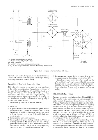
HI Heater energized by positive filter
H, Heater energized by negative filter Auxiliary
Th, Main thermistor D.C supply
Th, Ambient temperature compensated thermistor
R, R, R, etc To give the bridge linear resistanceitemp characteristic
Figure 12.28 A typical scheme of a heat sink circuit
between start and stalling conditions due to their low 5 Instantaneous ground fault by providing a zero
'overshoot' and can therefore detect a prolonged starting sequence relay in the residual circuit of the CTs.
or stalling condition without a trip. Therefore a motor protection relay, which may be
a 'normal time' or a 'long time', will be able to provide
Operation of heat sink thermistor relay through one unit a comprehensive motor protection,
generally requiring no more protection, except for a
This relay will operate whenever there is an unbalance surge protection, which may be needed for an HT
in the bridge circuit due to a change in the resistance of motor.
the main thermistor. because of the combined heating of
heaters H, and H,, as a result of overload, voltage 12.5.2 Solid-state relays
unbalance, inter-phase fault or a single phasing. The
operating time will depend upon the rate of heating, i.e. There are no moving parts in these relays (Figure1 2.29(a)).
the amount of overload or unbalance, thus giving an They employ static technology, Le. transistorized inte-
inverse time characteristic. grated circuits to achieve a thermal replica protection.
The following protections may be possible: To detect the presence of a negative sequence component,
filter circuits are used to separate positive and negative
1 Overload components I, and I, of the input current in each phase.
2 High set instantaneous overcurrent through the positive These currents are then used to produce voltages propor-
sequence network. An initial delay of a few cycles is tional to these currents. These voltages are then fed to a
introduced to avoid a trip during a start, whereas it squaring circuit to give a heating effect in the motor
will trip instantly on a phase fault, cable fault or a windings proportional to I,' and It. Figure 12.30(a) is
short-circuit. a typical schematic diagram of such a relay and a brief
3 Instantaneous unbalance current. operating description is given below.
4 Prolonged starting and stalling protection. When the The three line currents through the secondary of the
starting current of the motor does not fall within a three CTs, as shown in Figure 12.30(b), are fed to a
predefined starting time or up to the thermal withstand sequence filter network which separates the positive and
time of the machine, the relay will trip depending negative sequence components of the line currents drawn
upon the setting of its stalling detection unit. by the motor. These currents are then fed to separate