
Page 360 - Industrial Power Engineering and Applications Handbook
P. 360
Switchgear and controlgear assemblies 131335
13.1 Application Thus the basic purpose of a centralized power or
auxiliary control system is to achieve in service:
These assemblies are fitted with switching devices
(breakers, switches, fuse switches and contactors etc.) Ease of operation and control
and control and measuring instruments, indicating, More flexibility
regulating and protective devices etc. to transform the Ease of testing the electrical installation
assemblies into composite units, called control centres Ease of checking the control scheme, if any, on no-
to perform a number of functions in the field of distribution load before commencing the process.
and control of electrical power. Some of these functions More safety
may be one or more of the following: More reliability
To control, regulate and protect a generator and its 13.2 Types of assemblies
auxiliaries in a power station.
To control, regulate and protect the conversion, when
necessary, from one voltage to another, in a generating Depending upon their application, a switchgear or a
station or a switchyard for the purpose of further controlgear assembly can be one of the following types:
transmission or distribution of power.
Transmission of power. 1 Open Type This type of assembly is without an
Distribution of power. enclosure, as used in an outdoor switchyard or as mounted
on a pole, such as a gang-operated switch.
The basic idea of adopting to such a control system is 2 Metal enclosed type This type of assembly is
to broadly accomplish the following in normal operation: completely enclosed on all sides by sheet metal except
for the operating handles, knobs, instruments and
1 To have ease of operation and control a group of load inspection windows. The more conventional of them in
or control points from one common location. use may be classified as follows.
2 To monitor system operations for better coordination
between the various feeders and rapid control of the 13.2.1 Power control and distribution
feeders.
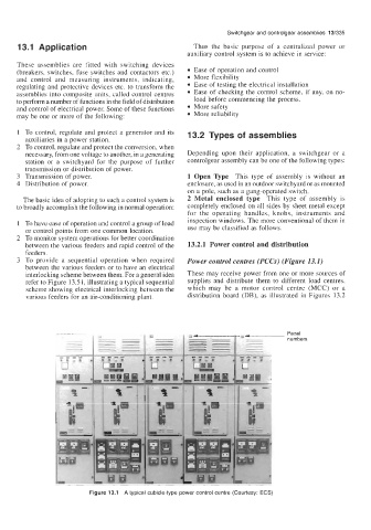
3 To provide a sequential operation when required Power control centres (PCCs) (Figure 13.1)
between the various feeders or to have an electrical
interlocking scheme between them. For a general idea These may receive power from one or more sources of
refer to Figure 13.5 1, illustrating a typical sequential supplies and distribute them to different load centres,
scheme showing electrical interlocking between the which may be a motor control centre (MCC) or a
various feeders for an air-conditioning plant. distribution board (DB), as illustrated in Figures 13.2
Panel
numbers
Figure 13.1 A typical cubicle-type power control centre (Courtesy: ECS)