
Page 364 - Industrial Power Engineering and Applications Handbook
P. 364
Switchgear and controlgear assemblies 13/339
Main Horizontal or any other parameter. Or it can be employed in
Busbars inverter logistics, when it is being used for the control
I I I of the drive itself. Figure 13.9 illustrates a basic logical
Control
buses
scheme.
J 3 Input and output interface This is the interface
between the controlling devices and the processor.
The input/output (YO) unit receives signals from the
input devices and transmits output action signals to
the controlling devices.
Note
A separate unit is used for programming and editing (e.g. a hand-
held programmer or a computer). For on-line editing, keyboards
are used. For on-line monitoring, a PLC is interfaced with a computer
and special software.
A logical controller is thus a more effective method of
replacing the auxiliary relays and is capable of performing
many more functions instantly.
‘E c A process requiring accurate and instant speed controls
must adopt static motor controls, described in Section
6.9, and their control schemes must be activated
through programmable logic controllers (PLCs) discussed
above.
Shielding of signals
It is important to prevent the control signals from becoming
corrupted by electromagnetic interference caused by the
power circuits, particularly those carrying the motor
currents from the machine to the power-cum-control panel
housing the drive and the PLC. During each switching
sequence, the motor will draw switching currents and
develop switching voltages. Even small electrostatic
interference may lead to malfunctioning of the drive.
Shielded (screened) control cables are therefore recom-
mended for this purpose for the control panels’ internal
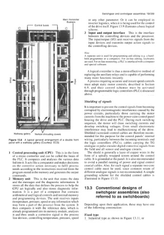
Figure 13.8 A typical general arrangement of a double front wiring, particularly between the incoming terminals and
panel with a walkway gallery (Courtesy: ECS) the logic controllers (PLCs), cables carrying the TG
analogue or pulse encoder digital corrective signals from
the field and all sensor and analogue circuits.
1 Central processing unit (CPU) This is in the form The shield is generally a layer of copper wires in the
of a micro controller and can be called the brain of form of a spirally wrapped screen around the control
the PLC. It computes and analyses the various data cable. It is grounded at the panel. It is also recommended
fed into it. It acts like a comparator and makes decisions to avoid a parallel running of power and signal control
on the corrective action necessary to fulfil process coaxial cables. Also, for each signal a separate two-core
needs according to the instructions received from the control cable must be used, since common return of
program stored in the memory and generates the output different analogue signals is not recommended. A simple
commands. grounding scheme for the shielded control cables is
2 Memory unit This is the unit that stores the data illustrated in Figure 13.10.
and the messages and the diagnostic information. It
stores all the data that defines the process to help the
CPU act logically and also stores diagnostic infor- 13.3 Conventional designs of
mation. It is a part of a computer that contains switchgear assemblies (also
arithmetical and logical controls and internal memory
and programming devices. The unit receives inputs referred to as switchboards)
(temperature, pressure, speed or any information which
may form a part of the process) from the system. It Depending upon their application, these may have one
then compares it with the reference data, which is of the following construction:
already programmed into its memory module, analyses
it and then sends a corrective signal to the process Fixed type
line devices, controlling temperature, pressure, speed 1 Industrial type as shown in Figure 13.11, or