
Page 365 - Industrial Power Engineering and Applications Handbook
P. 365
13/340 Industrial Power Engineering and Applications Handbook
(corrective ,-j output n
signals)
Iln;;r'
i[7?Jt
monitoring
1 - i Inputs
I -
I
I --c --L
CPU Memory I/O
interface
.................... module
Keyboard Programmable controller
Light sensitive base, which
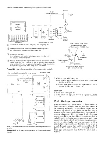
@ CPU or micro-controller. It is a computing and analysing unit breaks down and starts
conducting when the LED glows
@ Memory module which stores the reference data diagnostics LED .I ---_- L-.
and the operating programme of the process line
?-
@ Input/output interface: @ Input I y:
It is a relaying unit to receive actual parameters from the field signal
signal I
and relay out corrective signals L
@ A sort of electronic switch to protect the controller from control voltage Optical isolation> - -
module
spikes. They may occur because of very high control voltage (in the module Light emission
Light f
range of 24 to 220V d.c.) compared to the very low voltage circuit of the V
microprocessor, generally in the range of 5V d.c. or less An optical isolation scheme
(One for each signal)
Figure 13.9 A simple representation of a programmable controller
Screen of cable connected to panel ground Screened cable
2 Cubicle type which may be
(a) In a non-compartmentalized construction as shown
1 MCC cable Dane1 (b) A compartmentalized or modular construction as
in Figure 13.4, or
1, Draw-out
shown in Figures 13.1 and 13.3.
1 Semi-draw-out type, or
-G
2 Fully draw-out type, as shown in Figures 13.2 and
13.12.
13.3.1 Fixed-type construction
In a fixed construction, all the feeders in the switchboard,
feeding the various load points, are securely mounted in
the assembly and rigidly connected to the main bus. In
the event of a fault in one feeder on the bus side, a
shutdown of the entire switchboard may be required. A
process industry or critical loads can ill afford such an
arrangement. However, since this is the most cost-effective
switchboard, it is also the most common type and is used
extensively. It also suih all applications, except a process
industry or critical loads, which may not be able to afford
encoder = G a total shutdown or prolonged downtime in the event of
a fault. In such cases a draw-out type switchboard will
Note It is recommended to provide separate grounding for electronic
circuits prove to be a better choice as discussed below. A
Figure 13.10 A simple grounding scheme for the shielded control fixed-type construction may further be classified as
cables follows.