
Page 367 - Industrial Power Engineering and Applications Handbook
P. 367
13/342 Industrial Power Engineering and Applications Handbook
Light &
P0 tops
I
Chassis in
isolated
position-
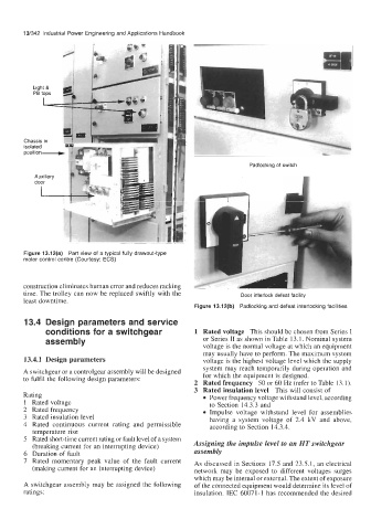
Padlocking of switch
...-
Figure 13.12(a) Part view of a typical fully drawout-type
motor control centre (Courtesy: ECS)
construction eliminates human error and reduces racking
time. The trolley can now be replaced swiftly with the Door interlock defeat facility
least downtime.
Figure 13.12(b) Padlocking and defeat interlocking facilities
13.4 Design parameters and service
conditions for a switchgear 1 Rated voltage This should be chosen from Series I
assembly or Series I1 as shown in Table 13.1. Nominal system
voltage is the normal voltage at which an equipment
may usually have to perform. The maximum system
13.4.1 Design parameters voltage is the highest voltage level which the supply
system may reach temporarily during operation and
A switchgear or a controlgear assembly will be designed for which the equipment is designed.
to fulfil the following design parameters:
2 Rated frequency 50 or 60 Hz (refer to Table 13.1).
3 Rated insulation level This will consist of
Rating Power frequency voltage withstand level, according
1 Rated voltage to Section 14.3.3 and
2 Rated frequency Impulse voltage withstand level for assemblies
3 Rated insulation level having a system voltage of 2.4 kV and above,
4 Rated continuous current rating and permissible according to Section 14.3.4.
temperature rise
5 Rated short-time current rating or fault level of a system
(breaking current for an interrupting device) Assigning the impulse level to an HT switchgear
6 Duration of fault assembly
7 Rated momentary peak value of the fault current As discussed in Sections 17.5 and 23.5.1, an electrical
(making current for an interrupting device) network may be exposed to different voltages surges
which may be internal or external. The extent of exposure
A switchgear assembly may be assigned the following of the connected equipment would determine its level of
ratings: insulation. IEC 6007 1-1 has recommended the desired