
Page 372 - Industrial Power Engineering and Applications Handbook
P. 372
Switchgear and controlgear assemblies 13/347
- - - - - &$ F! %
z,
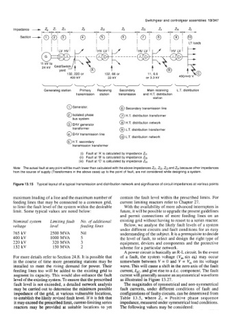
Impedance - Zl -31 z2 -32 z3 - zt3 - 4 zt4 z5 -
Section
, , LT loads
I I I
11 kV to
11 kV to
24 kV
yard @
yard
220
or
132, 220 or 0
132,
11, 6.6
kV
400 kV 33 kV or 3.3 kV 400/440 V
400
---v----
Generating station Primary Receiving Secondary Main receiving L.T. distribution
transmission station transmission and H.T. distribution
station
@Generator. @ Secondary transmission line
@Isolated phase @ H.T. distribution transformer
bus system
@ H.T. distribution network
@ EHV generator
transformer @ L.T. distribution transformer
@ EHV transmission line
@) L.T. distribution network
@ H.T. secondary
transmission transformer
(i) Fault at ‘A’ is calculated by impedance Ztl
(ii) Fault at ‘B is calculated by impedance 213
(iii) Fault at ‘C’ is calculated by impedance Zt4
Note The actual fault at any point will be much lower than calculated with the above impedances Ztl, &,Zt3 and 214 because other impedances
from the source of supply (Transformers in the above case) up to the point of fault, are not considered while designing a system.
Figure 13.15 Typical layout of a typical transmission and distribution network and significance of circuit impedances at various points
maximum loading of a line and the maximum number of contain the fault level within the prescribed limits. For
feeding lines that may be connected to a common grid, current limiting reactors refer to Chapter 27.
to limit the fault level of the system within the desirable With the availability of more advanced interrupters in
limit. Some typical values are noted below: future, it will be possible to upgrade the present guidelines
and permit connections of more feeding lines on an
Nominal system Limiting fault No. of additional existing grid without having to resort to a series reactor.
voltage level feeding lines Below, we analyse the likely fault levels of a system
under different circuits and fault conditions for an easy
765 kV 2500 MVA Nil understanding of the subject. It is a prerequisite to decide
400 kV 1000 MVA 5 the level of fault, to select and design the right type of
220 kV 320 MVA 3 equipment, devices and components and the protective
132 kV 150 MVA 2 scheme for a particular network.
A power circuit is basically an R-L circuit. In the event
For more details refer to Section 24.8. It is possible that of a fault, the system voltage (V, sin 4) may occur
in the course of time more generating stations may be somewhere between V = 0 and V = V, on its voltage
installed to meet the rising demand for power. Their wave. This will cause a shift in the zero axis of the fault
feeding lines too will be added to the existing grid to current, Zsc, and give rise to a d.c. component. The fault
augment its capacity. This would also enhance the fault current will generally assume an asymmetrical waveform
level of the existing system. To ensure that the prescribed as illustrated in Figure 13.27.
fault level is not exceeded, a detailed network analysis The magnitudes of symmetrical and non-symmetrical
may be carried out to determine the minimum possible fault currents, under different conditions of fault and
impedance of the grid, at various vulnerable locations, configurations of faulty circuits, can be determined from
to establish the likely revised fault level. If it is felt that Table 13.5, where Z1 = Positive phase sequence
it may exceed the prescribed limit, current-limiting series impedance, measured under symmetrical load conditions.
reactors may be provided at suitable locations to yet The following values may be considered: