
Page 368 - Industrial Power Engineering and Applications Handbook
P. 368
Switchgear and controlgear assemblies 13/343
Female portion Male portion Terminals disengaged Terminals engaged
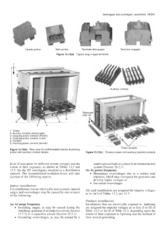
Figure 13.13(a) Typical plug-in-type terminals
1
I
Auxiliary contacts
r
3 4
1. Trolley
2. Auxiliary contacts (sliding type)
3. Outgoing power contacts (female)
4. Outgoing power contacts (male)
5. Insulator
6. Incoming power contacts (female)
Power contacts
Figure 13.13(b) Rear view of a withdrawable chassis illustrating
power and auxiliary contact details Figure 13.1 3(c) Drawout power and auxiliary (control) contacts
level of insulation for different system voltages and the sudden ground fault on a phase in an isolated neutral
extent of their exposure, as shown in Tables 13.2 and system (Section 20.2.1)
13.3, for the HT switchgears installed in a distribution (b) At power frequency
network. The recommended insulation levels will take Momentary overvoltages due to a sudden load
account of the following aspects. rejection, which may overspeed the generator and
develop higher voltages or
Sustained overvoltages
Indoor installations
For installations that are electrically non-exposed, internal All such installations are assigned the impulse voltages
surges and overvoltages may be caused by one or more as in list I of Tables 13.2 and 13.3.
of the following:
Outdoor installations
(a) At surge frequency Installations that are electrically exposed to lightning
Switching surges, as may be caused during the are assigned the impulse voltages as in lists I1 or 111 of
switching operation of an inductive circuit (Section Table 13.2 or list I1 of Table 13.3, depending upon the
17.7.2) or a capacitive circuit (Section 23.5.1) extent of their exposure to lightning and the method of
Grounding overvoltages, as may be caused by a their neutral grounding.