
Page 373 - Industrial Power Engineering and Applications Handbook
P. 373
13/348 Industrial Power Engineering and Applications Handbook
-
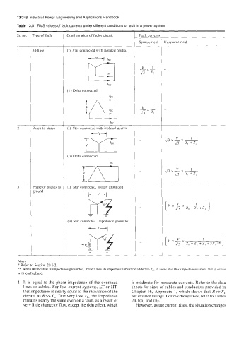
Table 13.5 RMS values of fault currents under different conditions of fault in a power system
Sr. no. rype of fault Configuration of faulty circuit Fault currents
~~
Symmetrical 1 Unsymmetrical
~ ~ I
1 3-Phase (i) Star connected with isolated neutral
;rf
kc
I-VI
kc
(ii) Delta connected kc
.
2 Phase to phase (i) Star connected with isolated neutral
t-- "--l
(ii) Delta connected
kc
i
3 Phase or phases tc (i) Star connected, solidly grounded
ground
I- "I
(i* V z, + Z? + Z" I
I
(ii) Star connected, impedance grounded
I- V I
3*xJ-x 1 1
[ J5 z, + z2 + Z" + 3x, **
Notes
* Refer to Section 20.6.2
** When the neutral is impedance grounded, three times its impedance must be added to Z,, in view that this impedance would fall in series
with each phase.
1 It is equal to the phase impedance of the overhead is moderate for moderate currents. Refer to the data
lines or cables. For low current systems, LT or HT, sheets for sizes of cables and conductors provided in
this impedance is nearly equal to the resistance of the Chapter 16, Appendix 1, which shows that R >>XL
circuit, as R>>XL. Due very low XL, the impedance for smaller ratings. For overhcad lines, refer to Tables
remains nearly the same even on a fault, as a result of 24.l(a) and (b).
very little change of flux, except the skin effect, which However, as the current rises, the situation changes