
Page 378 - Industrial Power Engineering and Applications Handbook
P. 378
Switchgear and controlgear assemblies 13/353
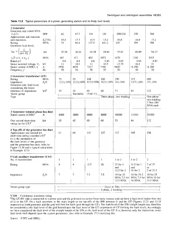
Table 13.8 Typical parameters of a power generating station and its likely fault levels
1 Generator
Generator size (rated MVA
x p.f.) MW 60 67.5 110 120 200/2 10 250 500
Approximate sub-transient
unit reactance, X,"(%) 15.4 17.7 15.9 13.2 16.8 16.9 17.2
Rating MVA 75 84.4 137.5 141.2 247 294 588
Generator fault level,
Isc = (*) kA 25.56 26.21 45.39 58.94 53.87 60.89 94.17
[a x Is, 1 MVA 487 477 865 1072 1470 1740 3425
x
vr
Rated p.f. 0.8 0.8 0.8 0.85 0.85 0.85 0.85
Stator nominal voltage, V, kV 11 10.5 11 10.5 15.75 16.5 21
Stator current (CMR)a, I, A 3936 1639 7217 7780 3050 0 290 6 200
Frequency, f HZ 50 50 50 50 50 50 50
2 Generator transformer (GT)
Rating MVA 75 85 140 140 250 315 500
Impedance Zp% 12.5f 109 12.5 f 104 12.5 f 10% 12.5f 104 14+ 10% 14.5f 10% 15* 10%
Generator side fault level,
considering the lower
tolerance of impedance, kAb 35 42 65 68 73 34 I22
Vector group - (Ynd 11)-
Staddelta
t---
SPe Three-pha two windin 3ne-phase
.wo-winding,
3 Nos 200
MVA each
3 Generator isolated phase bus duct
Rated current (CMR)a A 4000 5000 8000 8000 10000 I2 500 I8 000
One second short-time kA 35 42 65 68 73 $4 I22
rating (as for GT)~
4 Tap-offs of the generator bus duct
Approximate one-second kA 61 68 110 127 127 145 116
short-time rating (rounded ofOb
(it is the summation of
the fault levels of the generator
and the generator bus duct: refer to
Figure 13.18 and a typical calculation
in Example 13.3)
5 Unit auxiliary transformer (UAT)
No. of transformers 1 1 1 or 2 I or 2 l
Rating MVA 12.5 16 25 for 1 51.5 for 1 l of 25
and md )r
12.5 for 2 16 for 2 1. of 31.5
Impedance Zp% 7.5 7.5 10 for 25 10 for 31.5 LO for 25
MVA 7.5 foi VIVA 7.5 foi HVA 10 for
12.5 MVA I6 MVA 11.5 MVA
Vector group type c Dynl or Ddo >
< 3-phase, 2 winding >
aCMR - Continuous maximum rating
bThe GT HV side is connected to a power grid and the grid receives power from many sources and can have a fault level higher than that
of G or the GT. On a fault anywhere in the main length or the tap-offs of the IPB between G and the GT (Figures 13.21 and 13.18
respectively) both generator and the grid will feed the fault (grid through the GT). The fault level of the IPB straight length may therefore
be considered as the fault level of the grid limited upto the fault level of the GT (impedance of GT limiting the fault level). Accordingly
we have considered the fault level of the straight length of the IPB as the fault level of the GT. It is, however, only for illustration, exact
fault level shall depend upon the system parameters, also refer to Example 13.3 clarifying this.
Source NTPC and BHEL.