
Page 380 - Industrial Power Engineering and Applications Handbook
P. 380
Switchgear and controlgear assemblies 13/355
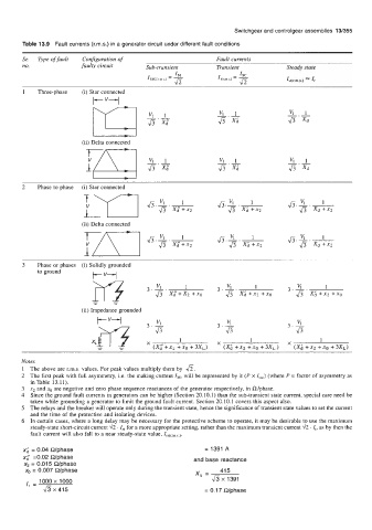
Table 13.9 Fault currents (rms.) in a generator circuit under different fault conditions
Sr. Type of fault Configuration of Fault currents
no. faulty circuit Sub-transient Transient Steady state
r(T1 61 Vl 1
Jr
K.L
xa
43 x4 fi Xd
(ii) Delta connected
2 Phase to phase (i) Star connected
(ii) Delta connected
J5.x.1 Js.K.1
Jr x; +x2 fi xd+x2
3 Phase or phases (i) Solidly grounded
to ground
t--v--l
(ii) Impedance grounded
Notes
1 The above are r.m.s. values. For peak values multiply them by &.
2 The first peak with full asymmetry, i.e. the making current IMr will be represented by 2 (P x I,,,) (where P = factor of asymmetry as
in Table 13.11).
3 x2 and xo are negative and zero phase sequence reactances of the generator respectively, in n/phase.
4 Since the ground fault currents in generators can be higher (Section 20.10.1) than the sub-transient state current, special care need be
taken while grounding a generator to limit the ground fault current. Section 20.10.1 covers this aspect also.
5 The relays and the breaker will operate only during the transient state, hence the significance of transient state values to set the current
and the time of the protective and isolating devices.
6 In certain cases, where a long delay may be necessary for the protective scheme to operate, it may be desirable to use the maximum
steady-state short-circuit current 42 . I,, for a more appropriate setting, rather than the maximum transient current 42 . I,, as by then the
fault current will also fall to a near steady-state value, Is,~r,,,,s,).
x; = 0.04 Wphase = 1391 A
x; =0.02 Wphase and base reactance
x, = 0.015 Wphase
x, = 0.007 Wphase Xb = 41 5
I, = 1000 x 1000 & x 1391
& x 415 = 0.17 Wphase