
Page 379 - Industrial Power Engineering and Applications Handbook
P. 379
13/354 Industrial Power Engineering and Applications Handbook
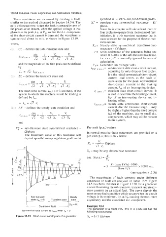
These reactances are measured by creating a fault, specified in BS 4999-140, for different grades.
similar to the method discussed in Section 14.3.6. The X; = transient state symmetrical reactance - Q/
only difference now is that the fault is created in any of phase.
the phases at an instant, when the applied voltage in that Since the interrupter will take at least three or
phase is at its peak, i.e. at V,, so that the d.c. component four cycles to operate from the instant of fault
of the short-circuit current is zero and the waveform is initiation, it is this transient reactance that is
symmetrical about its axis, as shown in Figure 13.19, more relevant for the purpose of short-circuit
calculations.
where,
X, = Steady-state symmetrical (synchronous)
(i) CL - defines the sub-transient state and reactance - Wphase.
r = series resistance of the generator, being too
small, 0.5-10% of the sub-transient reactance,
i.e. r << xd", is normally ignored for ease of
calculation.
and the magnitude of the first peak can be defined V, = Generator line voltage-volts
by Issc (r,,,s,) = sub-transient state short-circuit current,
occurring for only three or four cycles.
I, = I/Z.~ssC(rm*)
(ii) BL - defines the transient state and It is the initial symmetrical short-circuit
current, and serves as the basis of
calculation for the peak asymmetrical
short-circuit current or the making
current, I,, of an interrupting device.
The short-time current, Is, (1 or 3 seconds), of the It (c,m,s,J = transient state short-circuit current. It
system to which this machine would be feeding is is used to determine the breaking current,
defined by It,,,, Is,. of an interrupting device and its
heating effect.
... I,, = Jz . I, I,, (rm \,) = steady-state continuous short-circuit
(iii) AA' - defines the steady-state condition and current after the transient stage. It may
be slightly higher than the rated current
(I,) of the machine, due to small d.c.
components, which may still bc present
in the system.
and
Per unit (p.u.) values
X: = sub-transient state symmetrical reactance -
Wphase In normal practice these parameters are provided on a
The maximum value of this reactance will per unit (P.u.) basis only where
depend upon the voltage regulation grade and is
X, = & Wphase
113 .I,
Xb - may be any chosen base reactance
X
and X(p.u.) = -
Xb
X. (base kVA). 1000
=3. loo% etc,
(base V,?)
(see equation (13.3))
The magnitudes of fault currents under different
conditions of fault are analysed in Table 13.9. Figure
14.5 has been redrawn in Figure 13.20 for a generator
circuit illustrating the sub-transient, transient and steady-
state currents on an actual fault. The curve depicts the
most severe fault condition which occurs when the circuit
Sub-transient Steady voltage is the minimum, i.e. at Vo, causing the maximum
- state (16, = 0) Transient state state c asymmetry and the associated d.c. component.
I
- Duration of fault (bc = 0) Example 13.4
The generator of a 1000 kVA, 415 V, 3 IP DG set has the
Symmetrical fault current at V,,,, when /dc = 0 following reactances:
Figure 13.19 Short-circuit oscillogram of a generator Xd = 0.17 R/phase