
Page 374 - Industrial Power Engineering and Applications Handbook
P. 374
Switchgear and controlgear assemblies 13/349
gradually as a result of the proximity effect, which equipment against items 2 to 4, will hardly cause any reduction in
adds to the leakage flux of the circuit and diminishes the fault level of the system. The cables, irrespective of their lengths,
its reactance and the impedance. The decrease in contribute little to the impedance of the faulty circuit due to the
impedance contributes to limiting the fault level of negligible content of R compared to XL of the equipment,
the system. Refer to Table 30.7, which shows the .. Z= 4-
gradual decrease in X, with the current.
2 It is equal to the short-circuit impedance of transformers and R << X,
and motors. Now the machine undergoes a quick
change of flux, due to a change in the applied voltage :. z = x,
(it changes two peaks in one half of a cycle, Section This small content of R, however, helps in dampening the TRV,
1.2.1). The impedance during a fault is therefore (transient recovery voltages) (Section 17.6.2).
different from that during normal running. As standard
practice, the fault impedance is provided in p.u. by Z, = Negative phase sequence impedance
the machine manufacturers. The content of R is now Z, = Zero phase sequence impedance
far too low, compared to X, (Rc<X,), as is the p.f. of These impedances are provided by the manufacturers by
the faulty circuit. actual measurement. When these data are not readily
3 It is equal to the short-circuit impedance of the reactors. available, the approximations, as indicated in Table 13.6,
4 It is equal to the sub-transient impedance (Xf) of a may be assumed to complete the design work. The relay
generator as discussed later. settings for the actual protection may be made later.
As discussed above, it is usual practice to assume the
Note highest fault level of a network by considering the least
Considering an HT system, the use of cables with any of the possible impedance of the faulty circuit such as the
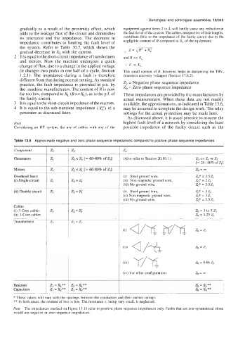
Table 13.6 Approximate negative and zero phase sequence impedances compared to positive phase sequence impedances
Component ZI I z2 ZO
Generators Z2 < Zl [= 60-80% of Z,] (Also refer to Section 20.10.1.) Z, << Z, or Z,
[e 25-40% of Zl]
Motors ZI Z2 < Z1 [E 6040% of ZI]
Overhead lines: (i) Steel ground wire, &* = 3.521
(i) Single circuit z1 I z, = z, (ii) Non-magnetic ground wire, 2,* = 22,
&* = 3.521
(iii) No-ground wire,
(ii) Double circuit ZI z, = z1 (i) Steel ground wire, &* = 5z1
(ii) Non-magnetic ground wire, &* = 321
(iii) No ground wire, &* = 5.5 zl
Cables
(i) 3-Core cables z1 z, = ZI 2,= 3 to 5 ZI
(ii) I-Core cables ~ Zo = 1.25 Z1
Transformers
2, = ZI
(iv) For other configurations 2,=m
Reactors ZI = XL** z, = XL** z, = XL**
Capacitors z, = xc** z, = xc** z, = xc**
* These values will vary with the spacings between the conductors and their current ratings.
** In both cases, the content of loss is low. The resistance r, being very small, is neglected.
Note The impedances marked on Figure 13.15 refer to positive phase sequence impedances only. Faults that are non-symmetrical alone
would use negative or zero sequence impedances.