
Page 371 - Industrial Power Engineering and Applications Handbook
P. 371
13/346 Industrial Power Engineering and Applications Handbook
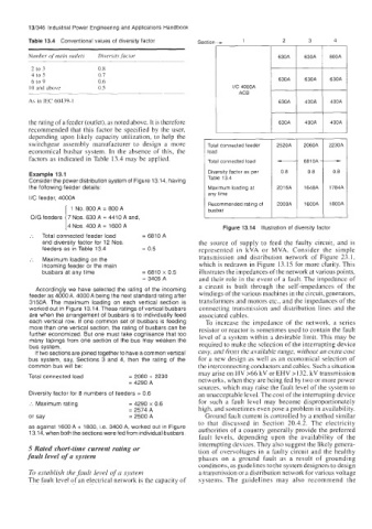
Table 13.4 Conventional values of diversity factor Section - 1 2 3 4
Number of main outlets Diversis factor 630A 630A 800A
2 to 3 0.8
4 to 5 0.7
6 to 9 0.6 630A 630A 630A
IO and above 0.5 l/C 4000A
ACB
As in IEC 60439-1 630A 400A 400A
the rating of a feeder (outlet), as noted above. It is therefore 630A 400A 400A
recommended that this factor be specified by the user,
depending upon likely capacity utilization, to help the
switchgear assembly manufacturer to design a more Total connected feeder 2520A 2060A 2230A
economical busbar system. In the absence of this, the load 681 OA -
factors as indicated in Table 13.4 may be applied. Total connected load
Example 13.1 Diversity factor as per 08 0.8 0.8
Consider the power distribution system of Figure 13.14, having Table 13 4
the following feeder details: Maximum loading at 201 6A 1648A 1784A
any time
I/C feeder, 4000A Recommended rating of 2000A 1600A 1800A
1 1 No. 800 A = 800 A busbar
O/G feeders 7 Nos. 630 A = 4410 A and,
4 NOS. 400 A = 1600 A
:. Total connected feeder load = 6810 A Figure 13.14 Illustration of diversity factor
and diversity factor for 12 Nos. the source of supply to feed the faulty circuit, and is
feeders as in Table 13.4 = 0.5 represented in kVA or MVA. Consider the simple
:. Maximum loading on the transmission and distribution network of Figure 23.1,
incoming feeder or the main which is redrawn in Figure 13.15 for more clarity. This
busbars at any time = 6810 x 0.5 illustrates the impedances of the network at various points,
= 3405 A and their role in the event of a fault. The impedance of
Accordingly we have selected the rating of the incoming a circuit is built through the self-impedances of the
feeder as 4000 A. 4000 A being the next standard rating after windings of the various machines in the circuit, generators,
3150A. The maximum loading on each vertical section is transformers and motors etc., and the impedances of the
worked out in Figure 13.14. These ratings of vertical busbars connecting transmission and distribution lines and the
are when the arrangement of busbars is to individually feed associated cables.
each vertical row. If one common set of busbars is feeding To increase the impedance of the network, a series
more than one vertical section, the rating of busbars can be resistor or reactor is sometimes used to contain the fault
further economized. But one must take cognisance that too level of a system within a desirable limit. This may be
many tapings from one section of the bus may weaken the
bus system. required to make the selection of the interrupting device
If two sections are joined together to have a common vertical easy, and from the available range, without an extra cost
bus system, say, Sections 3 and 4, then the rating of the for a new design as well as an economical selection of
common bus will be: the interconnecting conductors and cables. Such a situation
may arise on HV >66 kV or EHV >132. kV transmission
Total connected load = 2060 + 2230 networks, when they are being fed by two or more power
= 4290 A
sources, which may raise the fault level of the system to
Diversity factor for 8 numbers of feeders = 0.6 an unacceptable level. The cost of the interrupting device
:. Maximum rating = 4290 x 0.6 for such a fault level may become disproportionately
= 2574 A high, and sometimes even pose a problem in availability.
or say = 2500 A Ground fault current is controlled by a method similar
to that discussed in Section 20.4.2. The electricity
as against 1600 A + 1800, i.e. 3400 A, worked out in Figure authorities of a country generally provide the preferred
13.14, when both the sections were fed from individual busbars.
fault levels, depending upon the availability of the
interrupting devices. They also suggest the likely genera-
5 Rated short-time current rating or tion of overvoltages in a faulty circuit and the healthy
fault level of a system phases on a ground fault as a result of grounding
conditions, as guidelines to the system designers to design
To establish the fault level of a system a transmission or a distribution network for various voltage
The fault level of an electrical network is the capacity of systems. The guidelines may also recommend the