
Page 370 - Industrial Power Engineering and Applications Handbook
P. 370
Switchgear and controlgear assemblies 13/345
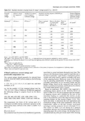
Table 13.3 Standard insulation (impulse) levels for range II voltage systems (V, > 245 kV)
Nominal Highest voltage Standard one-minute Standard switching impulse (250/2500 ps) Standard lightning
system for equipment power frequency withstand voltage impulse (1.2bOp)
voltage vm withstand voltage withstand voltage
phase to ground’
kV(r.m.s.)‘ kV(r.m.s.) kV(r.m.s.)’ Phase to ground Ratio to the phase Phase-to-
kV (peak)4 to ground peak phase kV (peak)4
value as in kV (peak)’
IEC 60071-1
750 1.50
275 300 380
850 1.50 1275
________~ 1275 I
850 1.50 1050
330 362 450
950 1.50 1425 1175
950 1.50 1425 1300
400 420 520
1050 1.50 1575 1425
550 620
800 830
1425 1.70 2420 I 2100
Notes As in IEC 60071-1 and IEC 60694
‘IEC 60071-1 has specified only V,,, values. Vr,,,s, is indicated based on the practices adopted by various countries.
’Lightning stress between the phases is not more than the lightning stress between a phase and the ground. For more details refer to IEC:
6007 1- 1.
’These values are applicable for
- Type tests - phase to ground
- Routine tests - phase to ground and phase to phase.
4More than one lightning impulse insulation level is indicative of the extent of exposure of an equipment to lightning surges.
’These values aremeancfor type tests only.
4 Rated continuous current ratings and more than its actual maximum demand at any time. The
permissible temperature rise reason is the liberal provisions made for loads that are to
be used occasionally - spare feeders, maintenance power
The current ratings should generally be selected from sockets and some reserve capacity available with most
series R-10 of IEC 60059 which comprises the following of the outgoing feeders. Moreover, some of the feeders
numbers; may be operating underloaded. To design a switchgear
assembly, particularly for its incoming feeder and the
1, 1.25, 1.6, 2, 2.5, 3.15, 4, 5, 6.3 and 8 etc. and their busbar ratings, based on the connected load would be
multiples in 10 neither economical nor prudent, and the protective scheme
too would under-protect such a system.
e.g. for the number 1.25 the standard ratings may be; Based on experience, IEC 60439-1 has suggested a
1.25,12.5, 125, 1250 or 12500A etc. IS 8084 has suggested multiplying factor, known as the ‘diversity factor’ as
the following ratings in amperes based on the above noted in Table 13.4. This factor depends upon the number
series: of outgoing circuits and is defined by the ratio of the
maximum loading on a particular bus section, at any
100,250,400,630, 800, 1250, 1600, 2000, 3150, time, to the arithmetic sum of the rated currents of all the
4000, 5000,6300, 8000, 10000, 12500 and 15000 etc.
outgoing feeders on that section (Figure 13.14). This
factor also helps to determine the most appropriate and
The temperature rise limits of the various parts of a economical ratings of the main equipment, such as the
switchgear assembly during continuous operation at the transformer, cables or the bus system, associated
rated current must conform to the values in Tables 14.5 switchgear and the protective devices (Example 13.1).
and 14.6. The values of Table 13.4 are based on a general
assumption, and may vary from one installation to another
Diversity factor depending upon the system design, the derating factors
The connected load of an electrical installation is generally considered and any other provisions made while choosing