
Page 361 - Industrial Power Engineering and Applications Handbook
P. 361
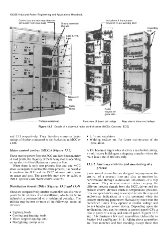
13/336  Industrial Power Engineering and Applications Handbook
             Control bus and wire way chamber                     Indications & instruments
             (shrouded from main bus)  1                       rmounted on an auxiliary door
                                      Gravity operated
                                                                                           Grounding


                                                                    f
                                                                j_-
                                                                 Roller
                                                                 mounts on             /+
                                                                 guide rails

                         Trolleys racked out        Front view of drawn out trolleys   Rear view of  drawn out trolleys
                         Figure 13.2  Details of a draw-out  motor control centre (MCC) (Courtesy:  ECS)

       and  13.3 respectively.  They  therefore  comprise  larger   Lifts and escalators
       ratings of feeders compared to the feeders in an MCC or   Welding  sockets etc.  for  future  maintenance  of  the
       a DB.                                            installation.
       Motor control centres (MCCs) (Figure 13.2)     A DB becomes larger when it serves a residential colony,
                                                      a multi-storey building or a shopping complex where the
       These receive power from the PCC and feed it to a number   main loads are of utilities  only.
       of load points, the majority of them being motors operating
       on an electrical installation  or a process line.   13.2.2 Auxiliary controls and monitoring of a
         When  there  is  only  one  process  line  and  one MCC
       alone is adequate to control the entire process, it is possible   process
       to combine the PCC and the MCC into one unit to save   Such control assemblies are designed to programme the
       on space and cost. The assembly may now be called  a   control  of  a  process  line  and  also  to  monitor  its
       PMCC (power-cum-motor  control centre).        performance  through  audiovisual  indications  or  a  trip
                                                      command. They  receive  control  cables  carrying the
       Distribution boards (DBs) (Figures 13.3 and 13.4)   different process  signals from the MCC, drives and the
                                                      process control devices  (such as temperature,  pressure,
       These are comparatively smaller assemblies and distribute   flow and speed-measuring devices) to actuate the required
       power to the utilities of an installation, which can be an   audiovisual  indications  or  a  trip  command  when  the
       industrial,  a commercial or a residential  complex. The   process-operating parameters fluctuate by more than the
       utilities may be one or more of the following  essential   predefined  limits.  They operate at control  voltage  and
       services:
                                                      do not  handle any power  device.  Depending  upon  the
                                                      application, they can be termed a control panel (CP), a
         Lighting loads                               mimic panel or a relay  and control panel. Figures  13.5
         Cooling and heating loads                    and 13.6 illustrate a few such assemblies. (Also refer to
         Water supplies (pump sets)                   Section 16.8 and Figure 16.11). All the above assemblies
         Firefighting  (pump sets)                    are floor  mounted  and free standing, except those that