
Page 477 - Industrial Power Engineering and Applications Handbook
P. 477
Testing of metal-enclosed switchgear assemblies 141451
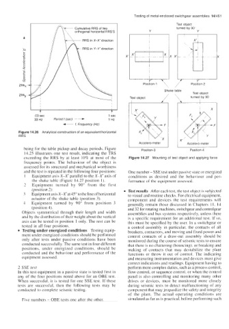
Test object
Cumulative RRS of two turned by 90'
orthogonal horizontal RRS'S Y Y
RRS in X-X direction
X
Y
Position-I , / Position-2
'\
Shake table
Test obiect
turned by 90
t t
.03 sec 1 sec
33 Hz Period t (sec) ~ + 1 Hz
f,
f- Frequency (Hz)
Figure 14.26 Analytical construction of an equivalent horizontal
RRS
being for the table pickup and decay periods. Figure I Position-3 I I Position-4 I
14.25 illustrates one test result, indicating the TRS
exceeding the RRS by at least 10% at most of the Figure 14.27 Mounting of test object and applying force
frequency points. The behaviour of the object is
assessed for its structural and mechanical worthiness
and the test is repeated in the following four positions: One number - SSE test under passive state or energized
I Equipment axis X-X' parallel to the X-X' axis of conditions as desired and the behaviour and per-
the shake tablc (Figurc 14.27 position 1). formance ol the equiprnent assessed.
2 Equipment turned by 90" from the first
(position 2). Test results After each test, the test object is subjected
3 Equipment axis X-X'at45" to the line of horizontal to visual and routine checks. For electrical equipment,
actuator of thc shakc tablc (position 3). component and devices the test requirements will
4 Equipment turned by 90" from position 3 generally remain those discussed in Chapters I 1. I4
(position 4). and 32 for rotating machines, switchgear and controlgear
Objects symmetrical through their length and width assemblies and bus systems respectively, unless there
and by the distribution of thcir weight about the vertical is a specific requirement for an additional test. If so,
axis can be tested in position 1 only. The rest can be this must be specified by the user. In a switchgear or
tested in all four positions. a control assembly in particular. the contacts of all
Testing under energized conditions Testing equip- breakers, contactors, and moving and fixed power and
ment under energized conditions should bc pcrformcd control contacts of a draw-out assembly should be
only after tests under passive conditions have been monitored during the course of seismic tests to ensure
conducted successfully. The same test in four different that there is no chattering (bouncing). or breaking and
positions, under energized conditions, should be making of contacts that may destabilize the plant
conducted and the behaviour and performance of the functions or throw it out of control. The indicating
equipment assessed. and measuring instrumentation and devices must give
correct indications and readings. Equipment having to
2 SSE test perform more complex duties, such as a process control,
In this test equipment in a passive state is tested first in flow control, or sequence control, or when the control
any of the four positions noted above for an OBE test. panel is also controlling and monitoring many other
When successful, it is tested for one SSE test. If these drives or devices, must be monitored more closely
tests are successful, then the following tests may be during seismic tests to detect malfunctioning of any
conducted to complete seismic testing. component that may jeopardize the safety and integrity
of the plant. The actual operating conditions are
Five numbers - OBE tests one after the other. simulated as far as is practical, before performing such