
Page 618 - Industrial Power Engineering and Applications Handbook
P. 618
Voltage surges-causes, effects and remedies 17/583
R Y B 17.10.6 Conclusion
1 1 1
Switching of an induction motor was typical of all to
illustrate the pheno-menon of switching surges in an
inductive circuit. The situation would remain the same
when switching a power system, transformer or power
cables also, in all conditions of loading (fully loaded,
under loaded or on no load). Switching surges in a
capacitor circuit is discussed in Section 23.5.1 with the
likely levels of voltage surges. Below we discuss the
insulation coordination and protection of other machines
and systems.
17.11 Theory of surge protection
(i nsu lat ion coordination)
The insulation of a current-carrying system, machine or
component is to provide it with the required insulation
level (BIL) to withstand system voltages during normal
operation, as well as temporary overvoltages (TOV) and
momentary voltage surges, up to a certain level, during
system disturbances. A safety margin is built into their
equipment by the manufacturers according to Tables 11.6,
14.1, 32.1(A), or 13.2 and 13.3 as standard practice to
sustain such voltages without failure or rupture of the
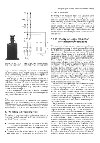
Figure 17.24(a) C-R- Figure 17.24(b) Typical power insulating system. Repeated application of such voltages,
type surge suppressor circuit of a C-R-type surge suppressor
even if they are below the BIL of the insulating system,
or longer duration of overvoltages, may lead to failure
or rupture of the insulating system as a result of insulation
surge, a low resistance path, and a means of absorbing
the excess energy of the surge to dampen it to a required fatigue. It is possible that in operation, TOVs or voltage
surges may exceed the safe (prescribed) power frequency
level while the surge capacitor arrests the steepness of or impulse withstand voltages (BIL) respectively, of the
the surge and reduces it to a desired r.r.r.v. power system or the terminal equipment. For the
The design of the C-R combination maintains a
negligible level of leakage current through the suppressor recommended safe insulation levels of different equip-
ment, refer to tables mentioned above.
in healthy conditions (to contain resistance loss). It is For instance, when lightning of, say, a nominal discharge
easily achieved, as C provides a near-open circuit in current of 10 kA strikes a 400 kV (r.m.s.) overhead line,
these conditions and permits only a very small leakage having a surge impedance of 350 Q, then two parallel
current to flow through it. waves will be produced each of amplitude 10 x 350/2 or
A C-R suppressor also helps to reduce the surge
1750 kV which may be more than the impulse withstand
impedance, Zs, of the circuit and thus limits the amplitude level of the system and cause a flashover between the
of Vt as discussed in Section 17.8.
conductors and the ground, besides damaging the line
insulators and the terminal equipment (Table 13.2). It is
Note therefore imperative that the system is protected against
Since a surge capacitor or a C-R combination surge suppressor such eventualities.
operates only at very high frequencies, such as those related to an
FOW, they maintain a near-open circuit for the arriving long-duration Surge protection, therefore, becomes essential when it
switching surges. They are thus required to handle only a moderate is felt that the surges generated during an operation at a
amount energy of an FOW and hence are suitable for such duties. particular installation may rise beyond the permissible
impulse withstand capacity (BIL) of the equipment. A
17.10.5 Setting fast-responding relays system that is prone to frequent occurrences of temporary
overvoltages. Induction motors for instance, which conform
No system is permitted to trip on the occurrence of a to the impulse withstand levels prescribed for this machine
momentary disturbance, such as by travelling surges of according to Table 11.6 may be supplemented by a surge
any kind. To overcome this: arrester or suppressor, when it is felt that the amplitude or
steepness (or both) of the surges in operation may exceed
The motor protection relay, as discussed in Section the prescribed levels. Coordination of insulation of the
12.5, is generally provided with a delay feature to equipment to be protected with that of the level of the
bypass these transients and delay the tripping by two protectivedevice, whichmay be a switchgear or alightning
or three cycles. arrester, is called insulation coordination. This would
The same is true for an overcurrent or a ground fault depend upon the type of installation, such as the type of
relay when used in circuits that are prone to surges. switching device and the length of the interconnecting