
Page 614 - Industrial Power Engineering and Applications Handbook
P. 614
Voltage surges-causes, effects and remedies 171579
results. The most appropriate impulse level must be chosen,
such as 3.5 p.u. for a rise time of 0.2 ,us, for the machines
to suit the system conditions, according to Table 11.6 for
rotating machines, or Tables 13.2 and 14.1 for switchgear
assemblies, Tables 32.1 (A) and 32.2 for bus systems and
Tables 13.2 and 13.3 for all other equipment. It should
be noted that steeply rising surges that fall within the
range of machine windings and interconnecting cables
alone are of relevance and not those that are faster or
slower. The steepness of the surge will determine its
propagation through the windings and its effects on the
coils or the interturns, such as whether the first coil,
second coil or the last coil or the first few or the last few
turns require protection as discussed earlier. Since the
actual installation may differ from that considered in
analytical studies, it is possible that the results obtained
may differ slightly from those analysed. It is therefore
ad\,isable to be more conservative in selecting the
amplitude and rise time of the prospective surges. While
the machine may be selected with a standard impulse
level, and if the probable amplitude and/or the rise time
are expected to be more stringent, separate protection
must be provided, as discussed later. The general practice
has been to insulate all the coils equally, according to the
standard impulse level of the machine. The following
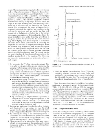
are preventive measures that can mitigate the effects of 0 @ @Motor (Surge impedance = Z,)
such surges:
MPR - Motor protection relay
1 By improving the PF of the interrupting circuit: This Figure 17.20 A number of motors connected in tandem on a
is to achieve extinction of the arc, i.e. interrupting the common bus
circuit at the first natural current zero, as far as possible,
and averting any restrikes. It may be noted that at
every current zero the arc due to contact separation 5 Protection against electrodynamic forces. These are
extinguishes and there is no conducting path between caused by transient currents, such ils on faults. and
the contacts until a restrike takes place. This can be mainly affect the overhangs or the parts of the windings
achieved in the following ways: that fall outside the stator slots. These parts are specially
Modern interrupting devices have an amount of braced and strengthened at the time of manufacture.
resistive interruption as a result of appropriate design
and choosing the right material for making contacts, Since the standard insulation level (BIL) of a machine,
(Section 19.2) which will help to moderate the highly equipment or a system is already defined, according to
inductive interrupting current. Some manufacturers Tables 11.6. 14.1, 32.1(A). 13.2 and 13.3, the machines
even provide a resistance shunt across the parting are accordingly designed for this basic insulation (BIL)
contacts. which forms part of the circuit during only. When the prospective surges are expected to be more
interruption only, similar to the theory of a surge severe than this, separate protection becomes imperative.
arrester (Section 18.1). This is particularly important for arotating machine which,
By installing p.f. improvement capacitors to besides being a dry equipment, also has only a limited
compensate the no-load magnetizing current of the space within the stator slots and hence has the smallest
circuit being switched (Section 23.13). These may BIL of all, as is evident from Table 11.6. compared to
be installed in the same switching circuit to switch Tables 14.1, 32.1(A) and 13.2. For its comprehensive
together with the inductive load. protection it can be considered in two parts.
2 In capacitor switching, introduction of an inductor
coil (Section 23.1 1) can contain not only the inrush 17.10.1 Major insulation area
current but also tame the current phasor to shift closer
to the voltage and thus limit theTRV on an interruption. This is the winding insulation to the body, which is more
3 By selecting the rating of the interrupting device as vulnerable to prospective voltage peaks, V,. as a result of
close to the full-load current of the system or machine TRVs. When the TRV exceeds the BIL of the machine,
as possible. An excessive rating than necessary may it can be dampened to a safe limit with the use of a surge
have tendency towards current chopping. arrester, say, from peak a, to u7, as illustrated in Figure
4 More care needs to be taken when there are a number 17.21. Details of a surge arrester and the procedure for
of such motors connected on the same bus and switched its selection are discussed below. See also Example 17.6.
in tandem, tending to multiply the switching effects The selection of the arrester will also depend upon
(Figure 17.20). the method of star (neutral) formation of the stator’s